The Counterfeit Coin Detector Patent Archive

Every device ever patented to catch a bad coin

All 129 patents

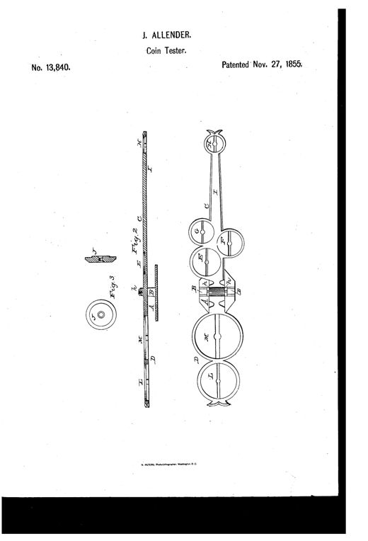
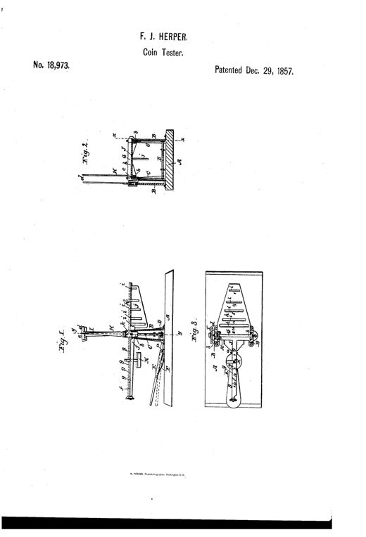
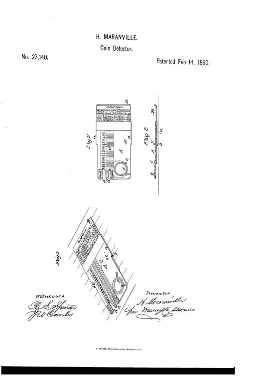
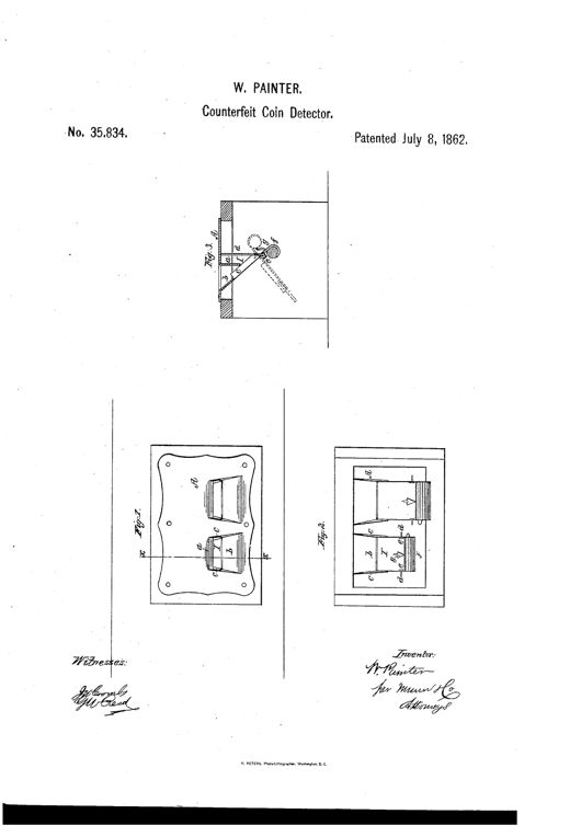
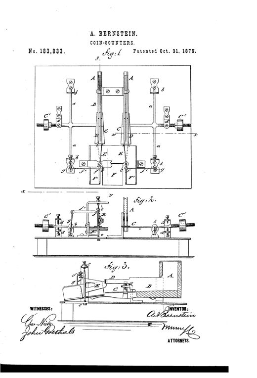
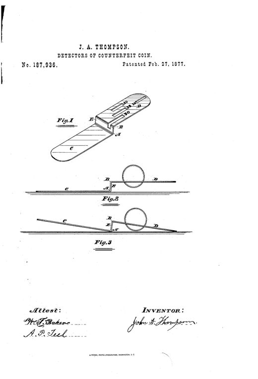
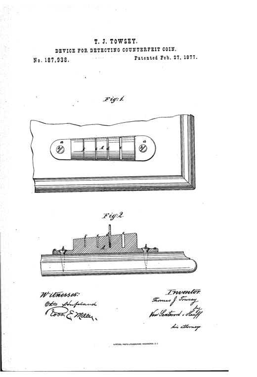
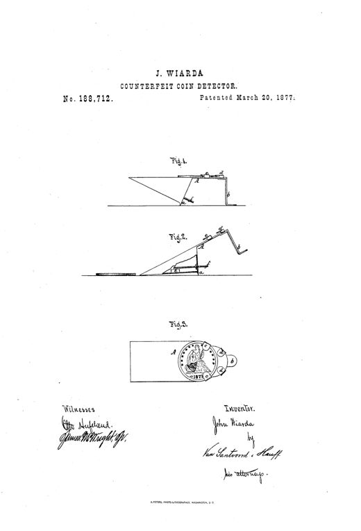
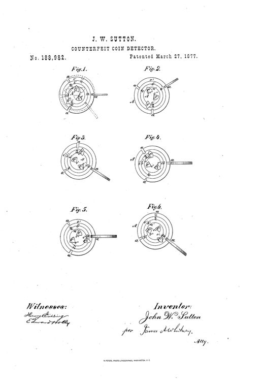
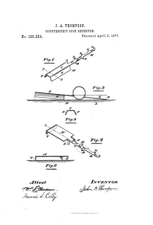
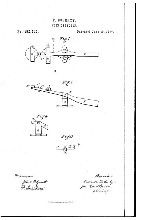
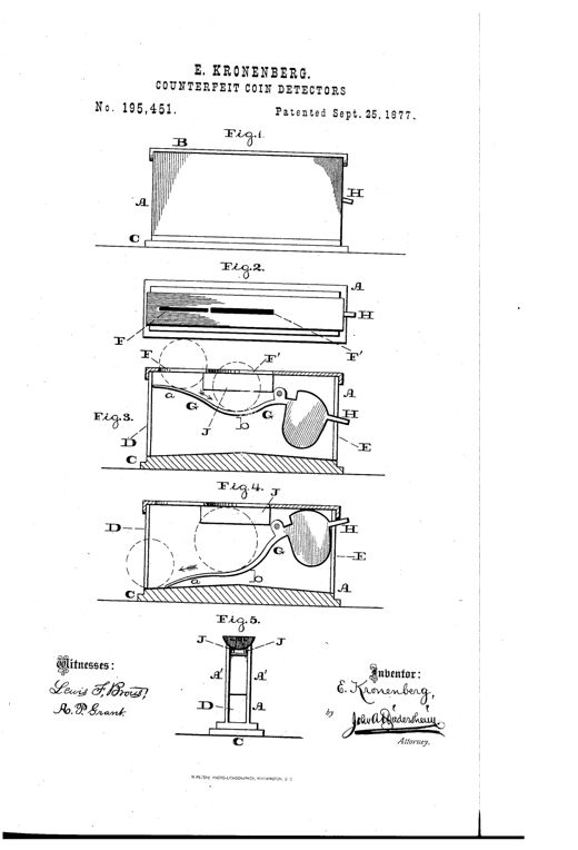
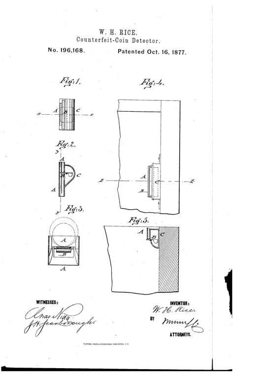
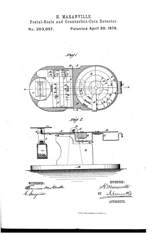
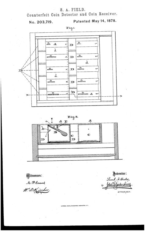
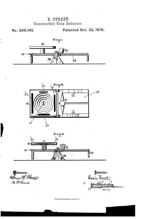
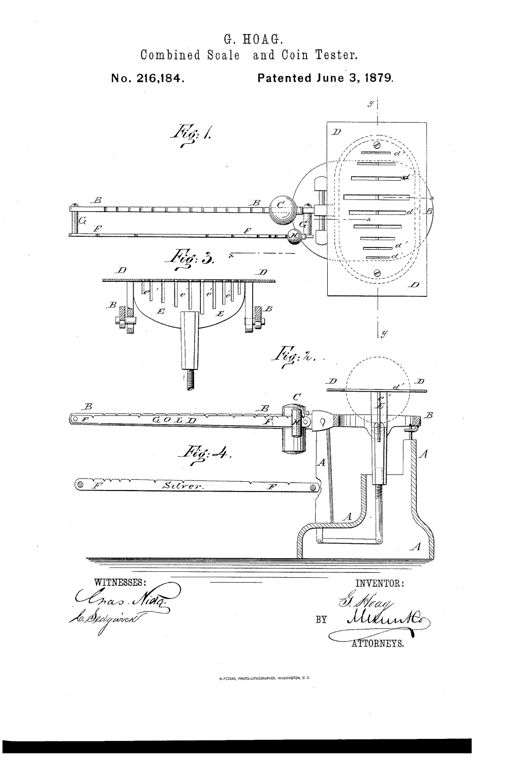
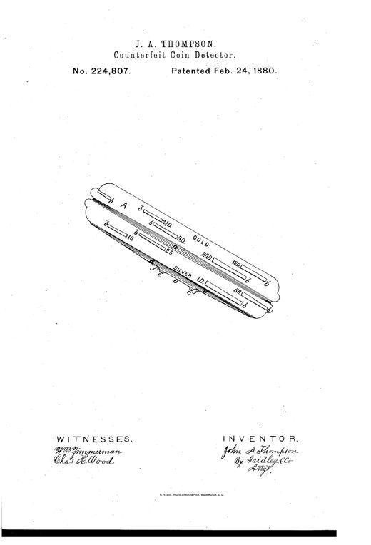
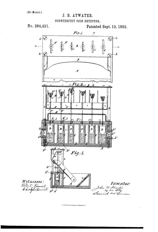
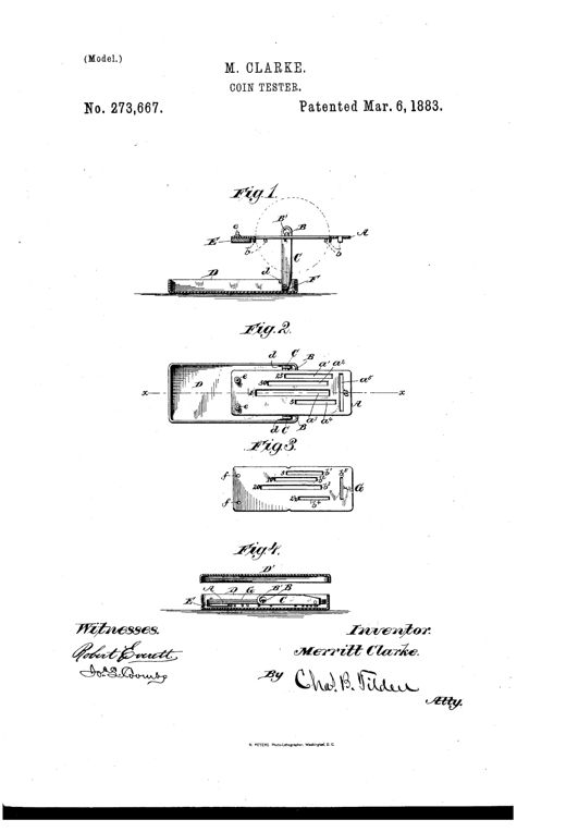
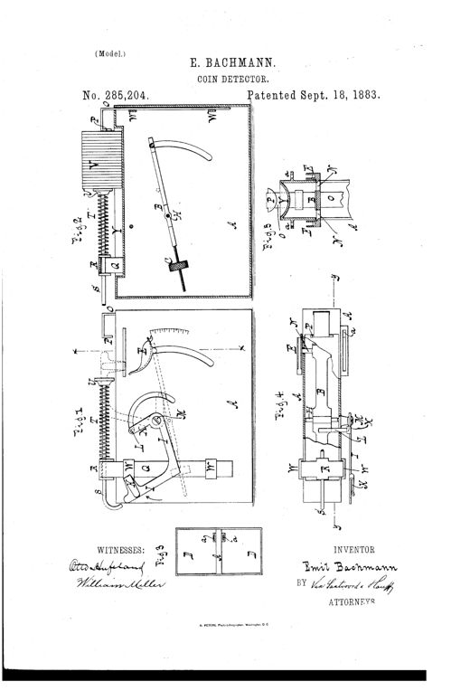
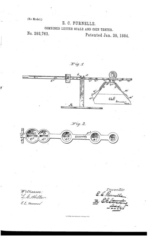
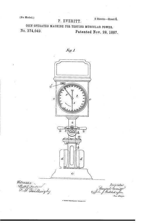
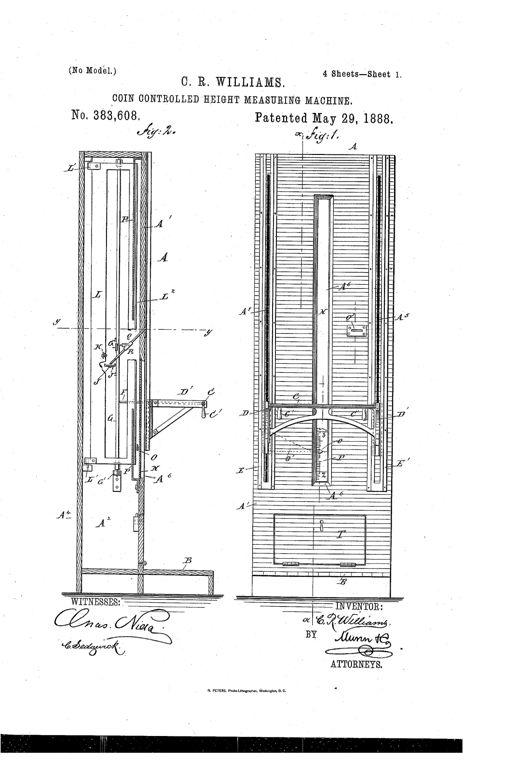
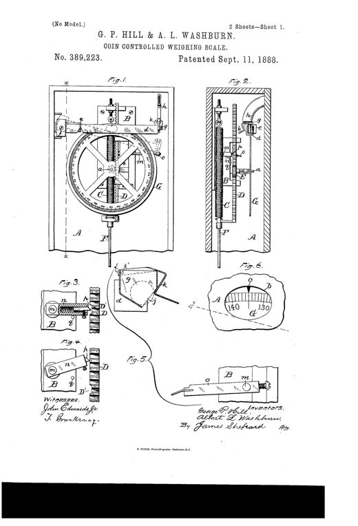
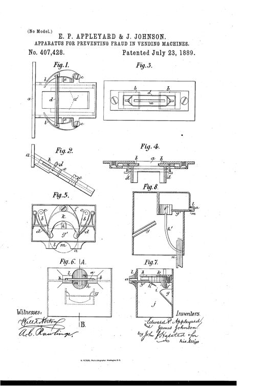
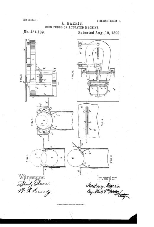
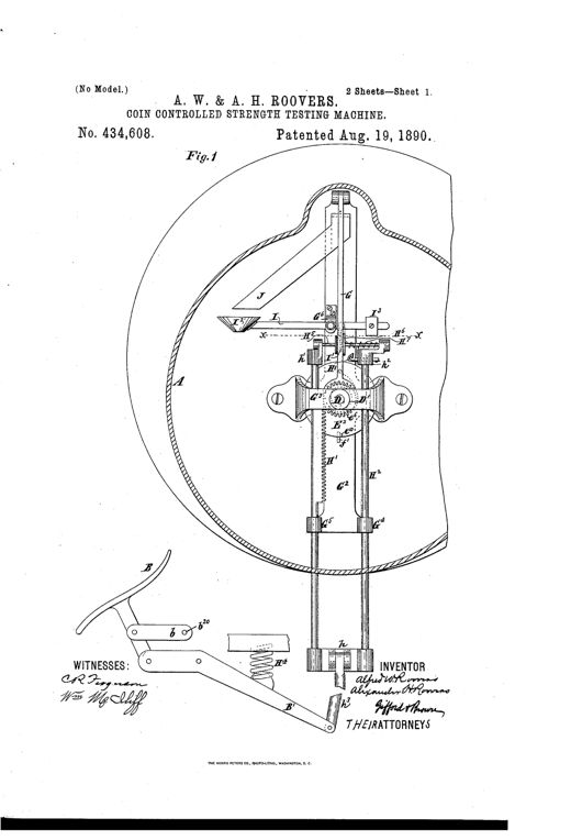
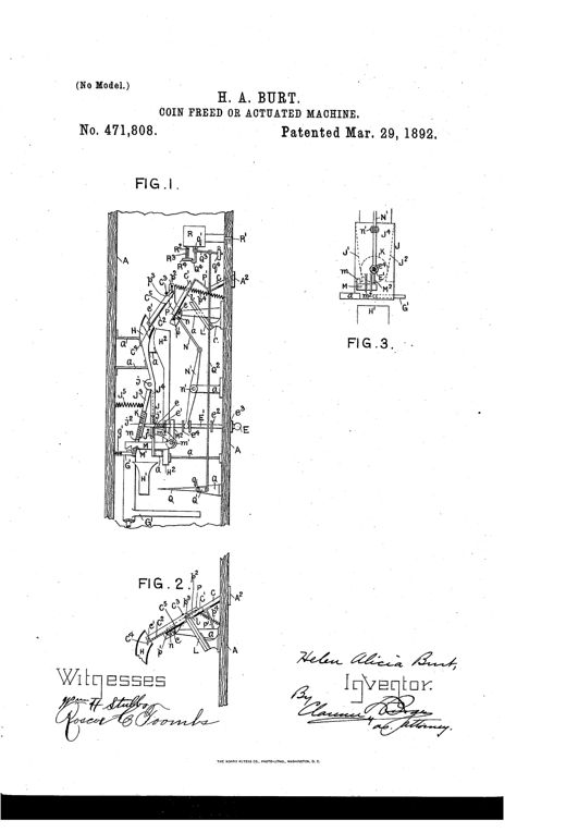
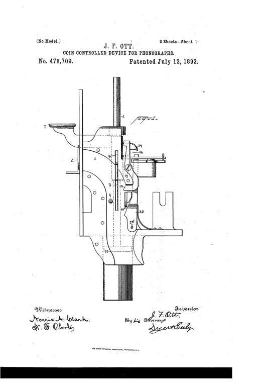
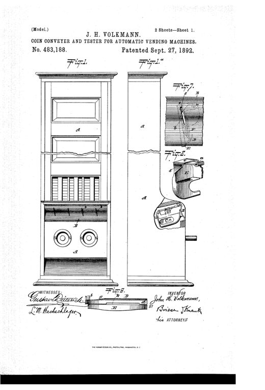
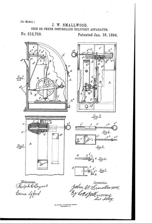
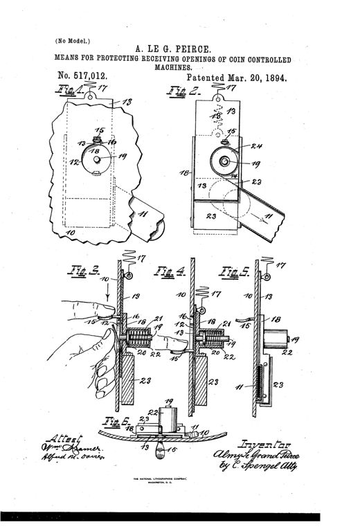
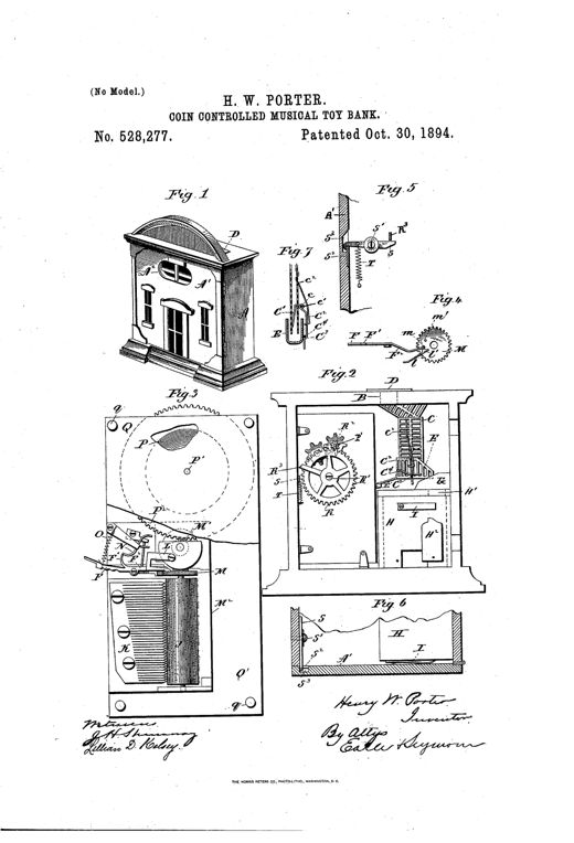
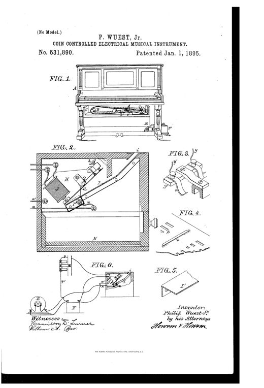
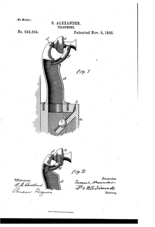
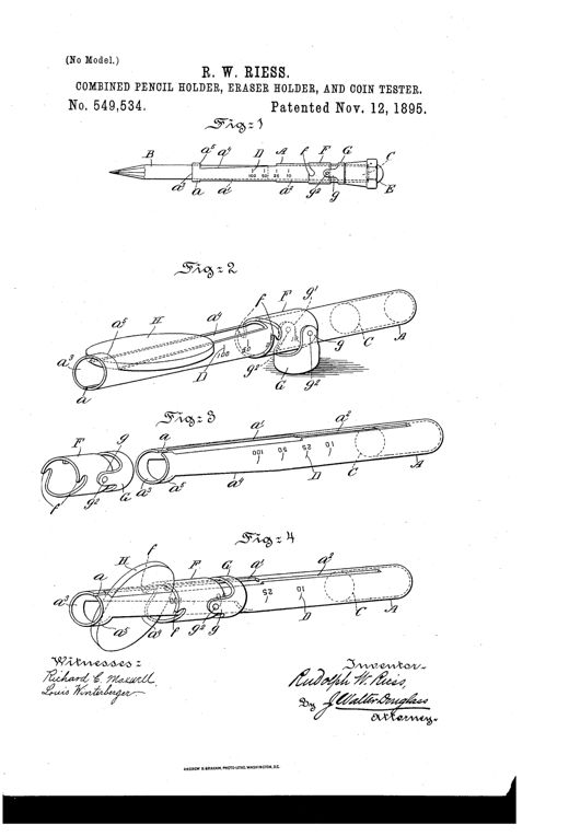
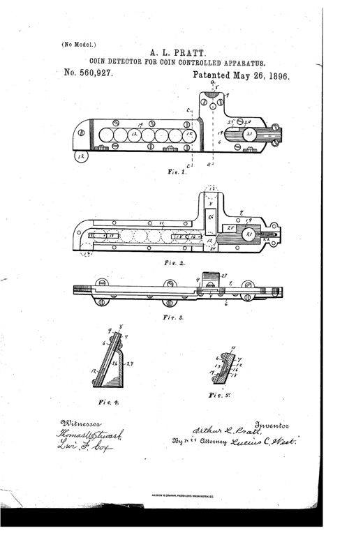
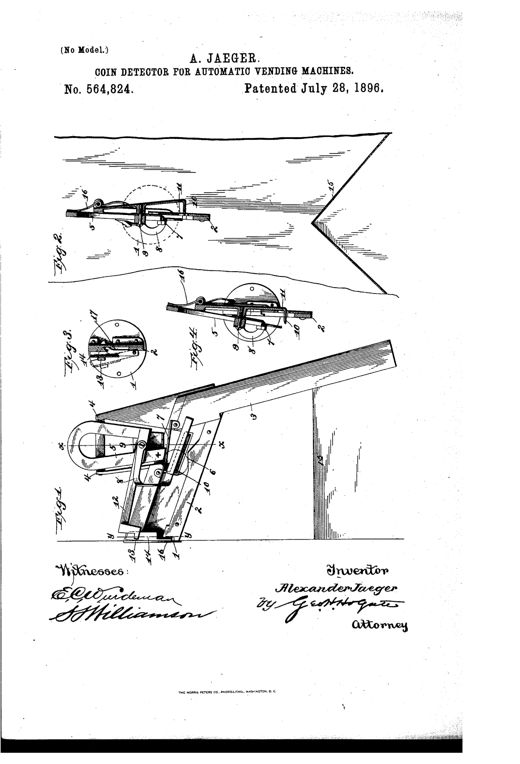
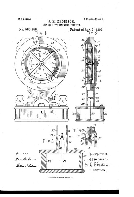
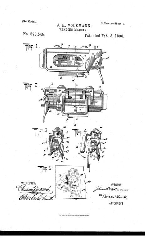
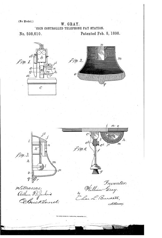
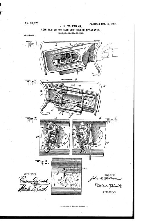
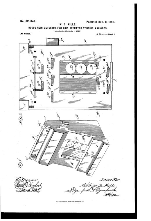
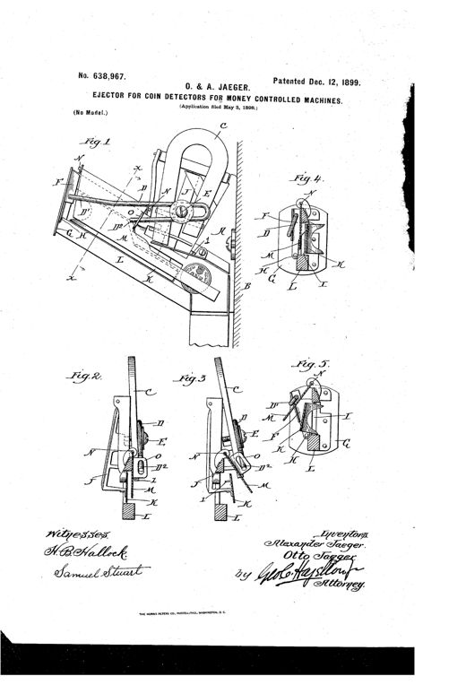
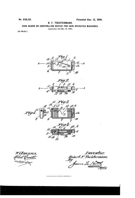
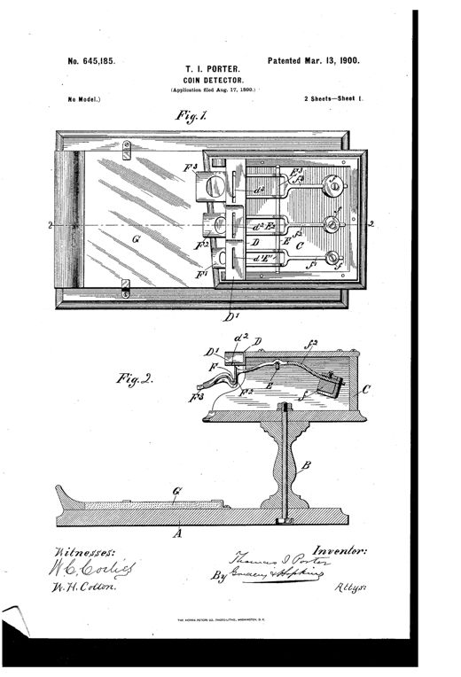
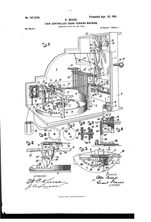
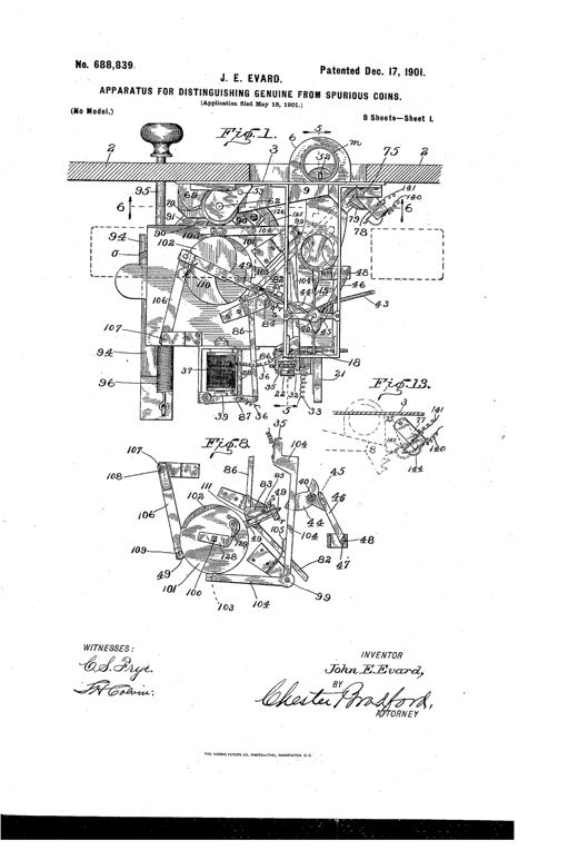
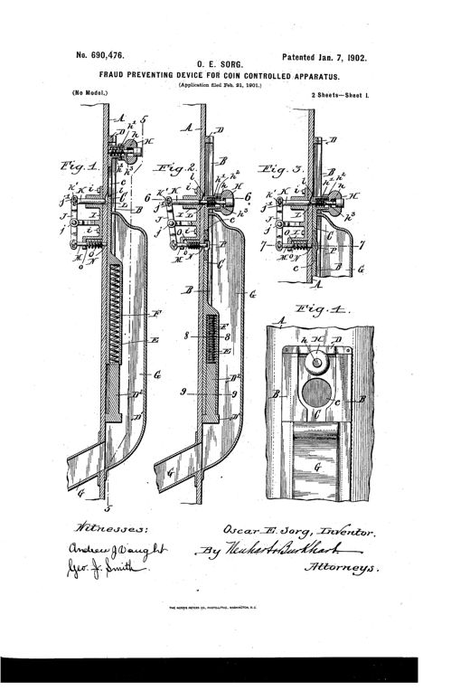
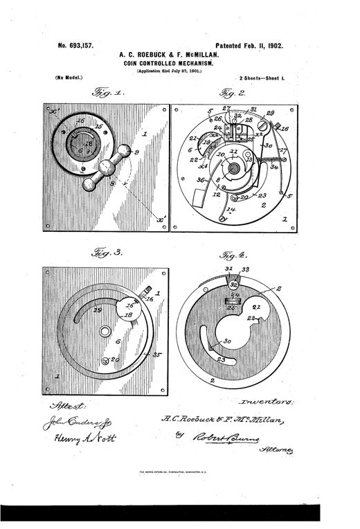
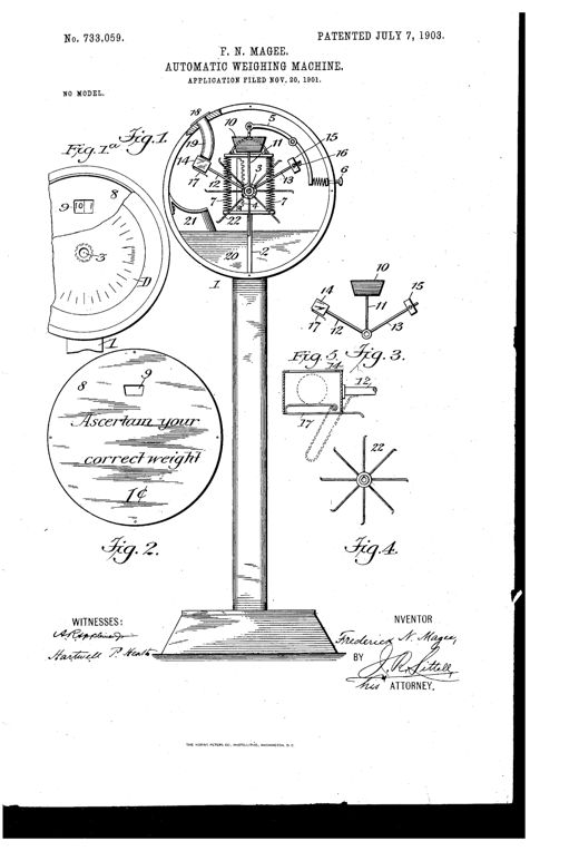
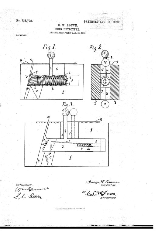
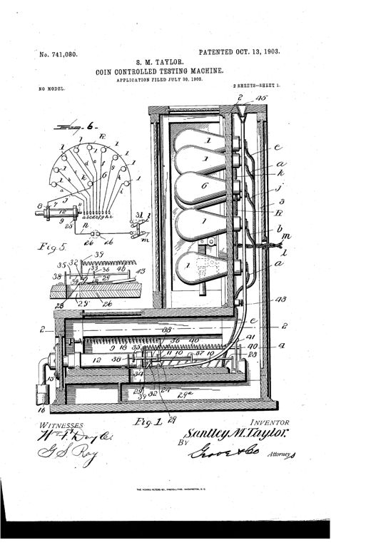
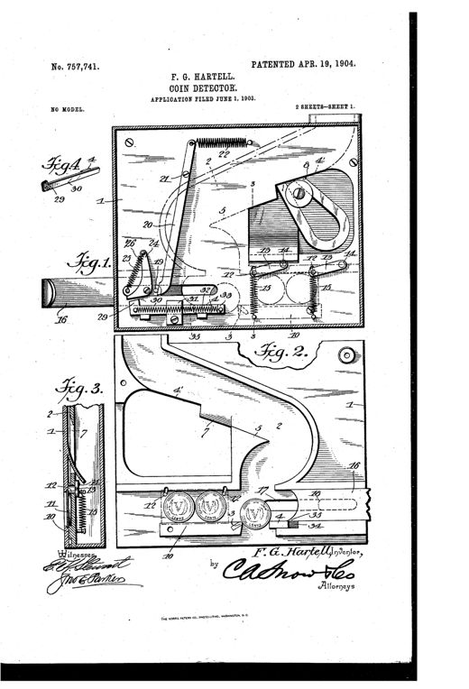
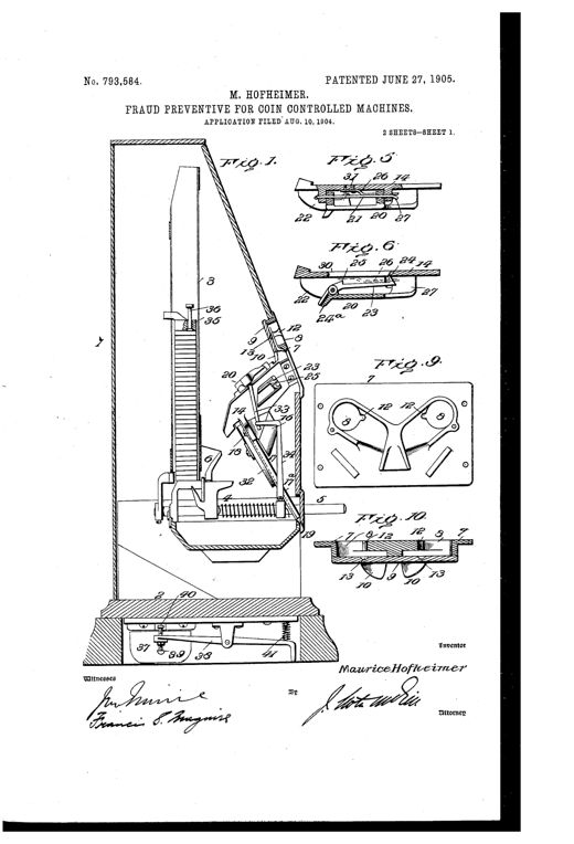
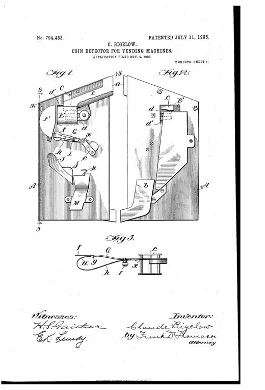
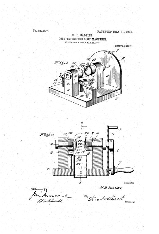
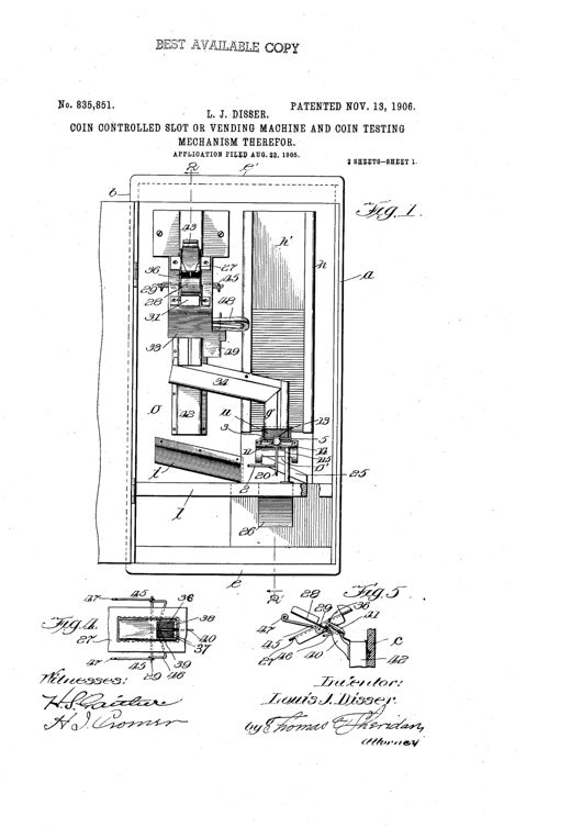
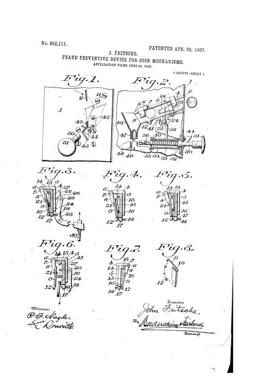
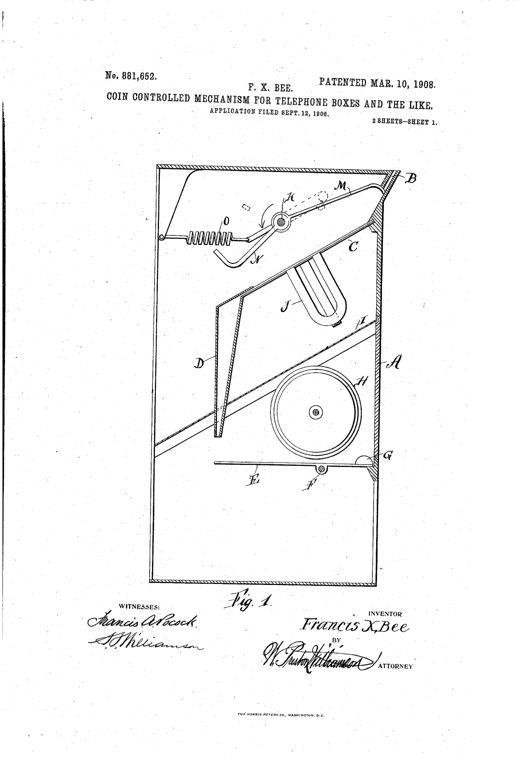
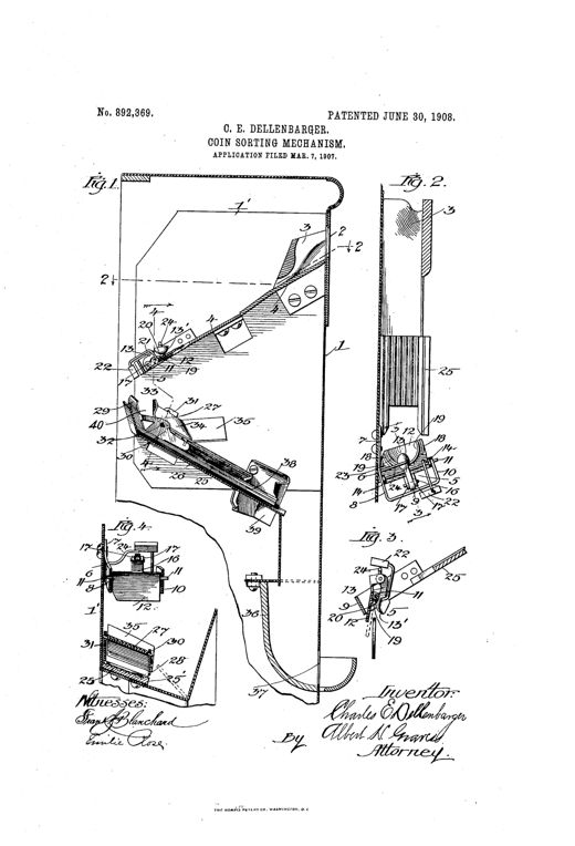
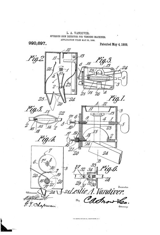
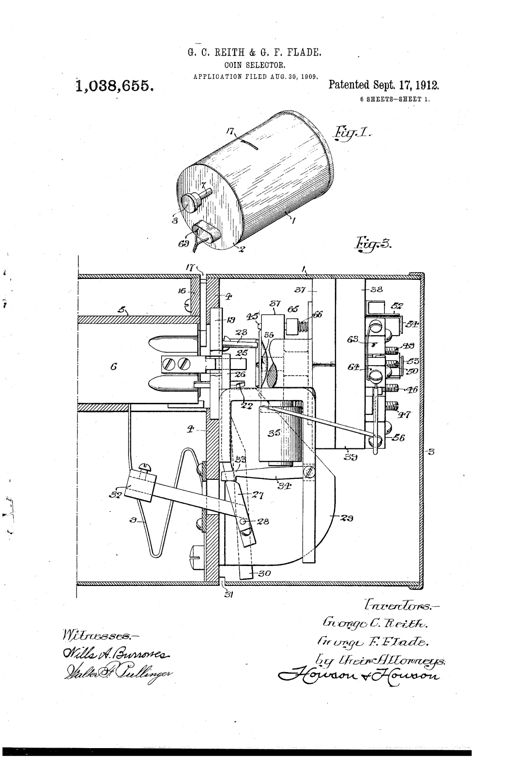
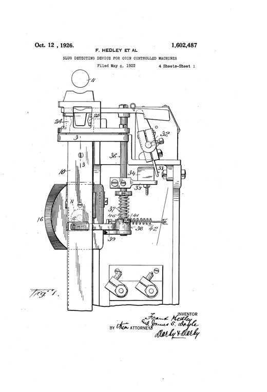
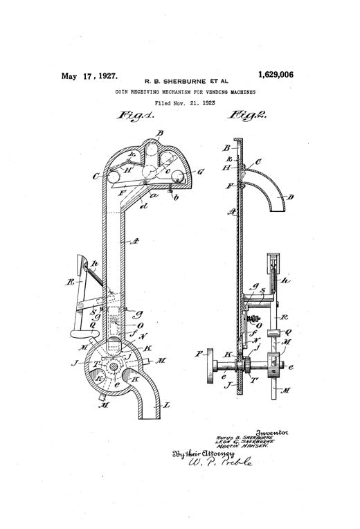
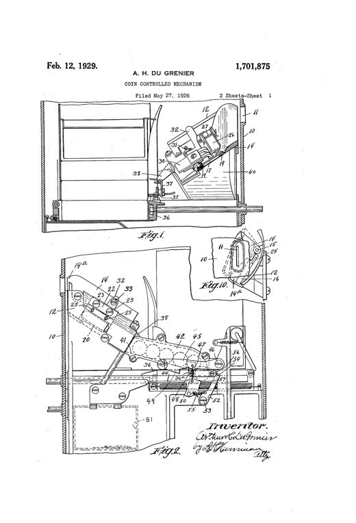
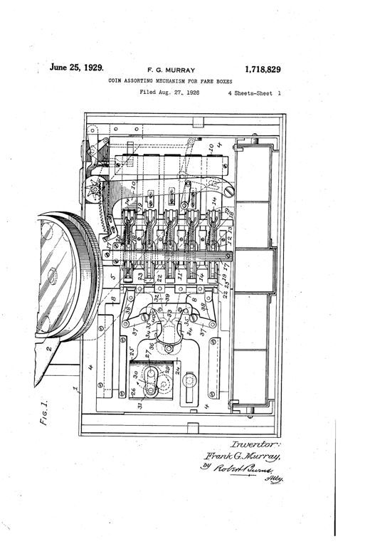
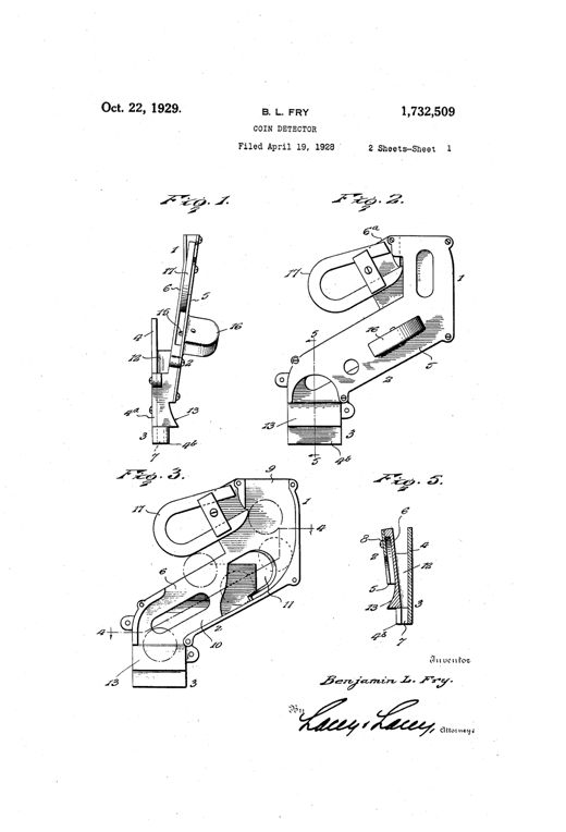
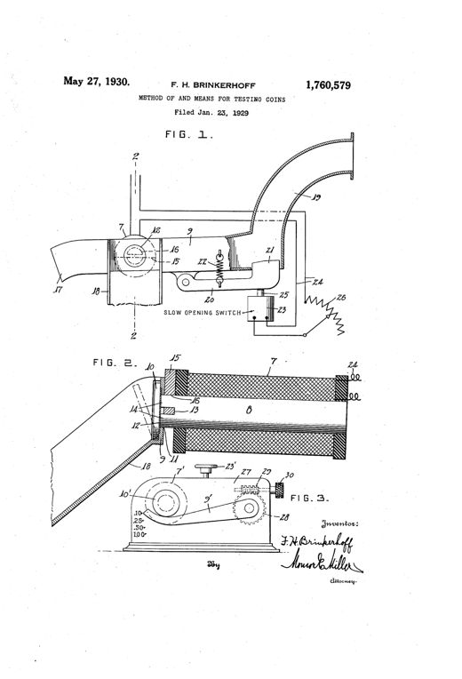
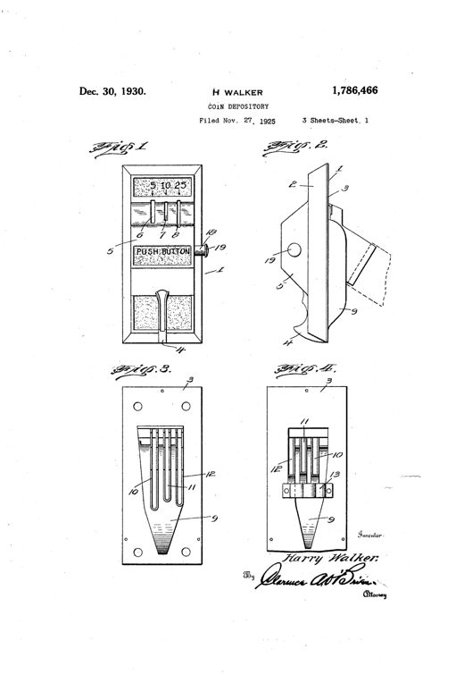
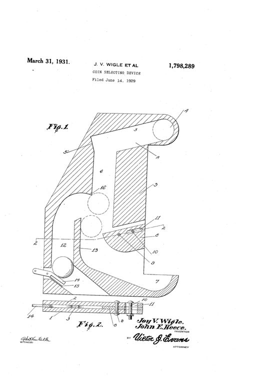
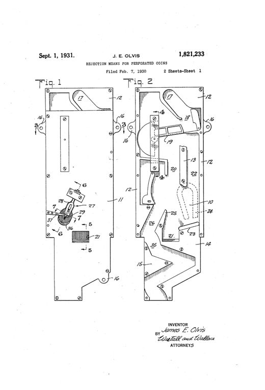
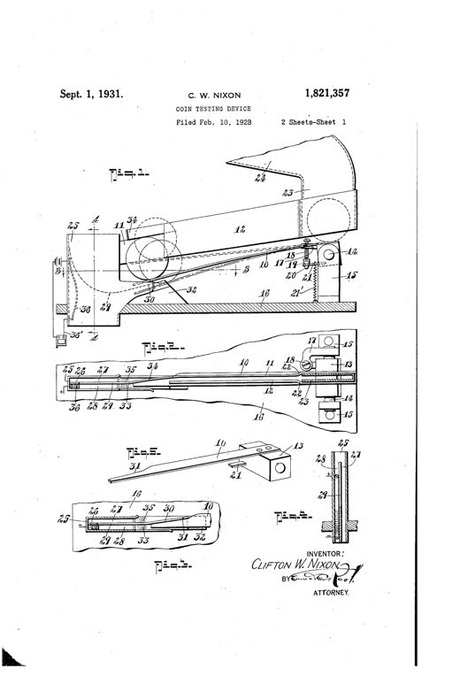
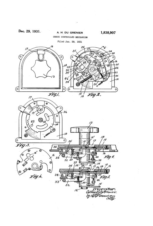
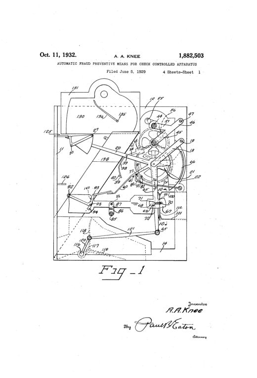
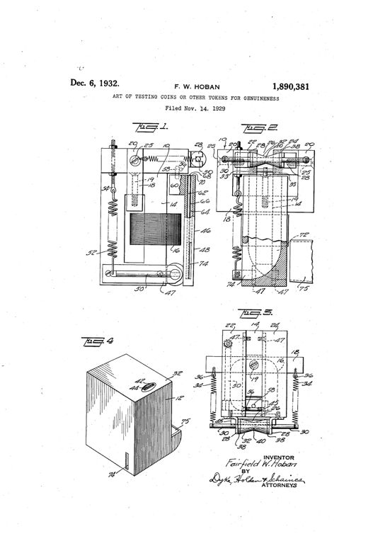
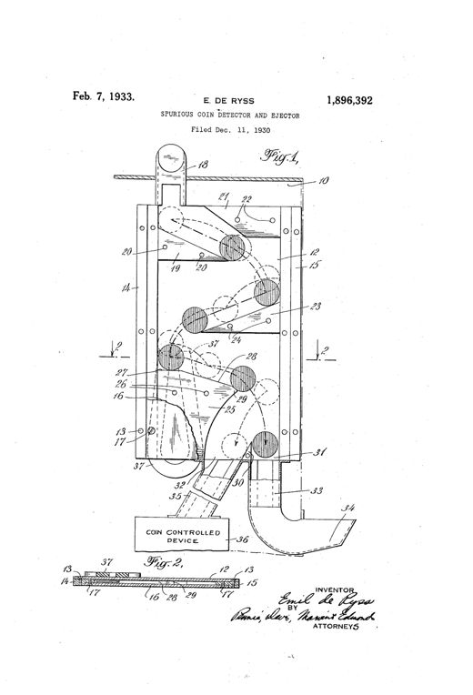
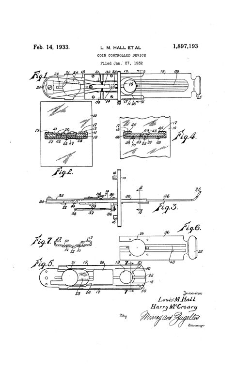
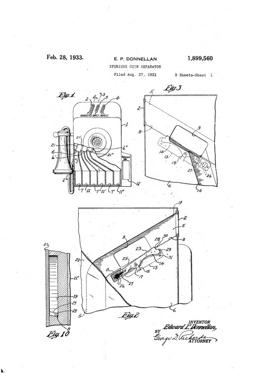
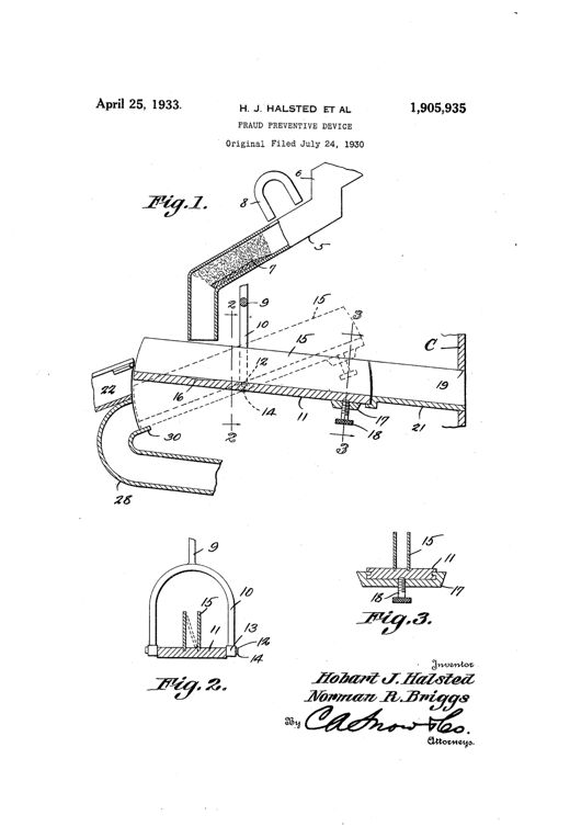
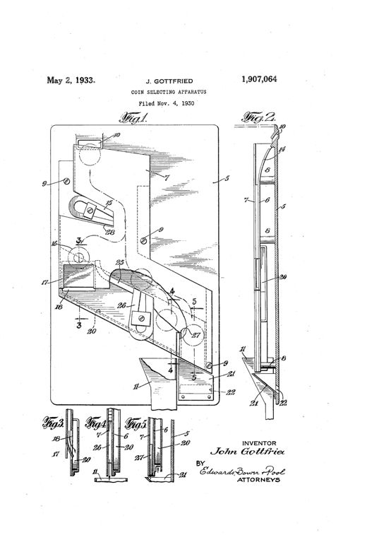
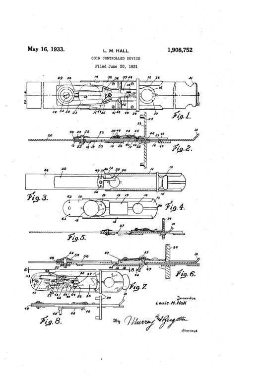
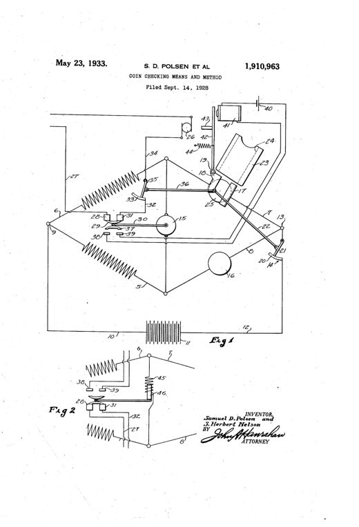
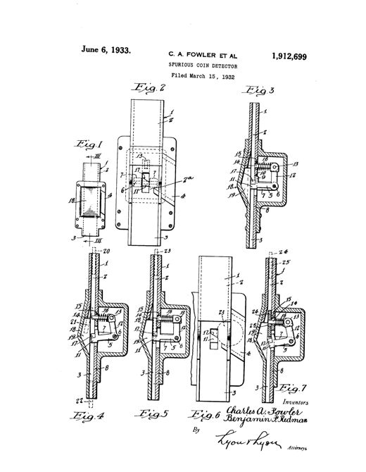
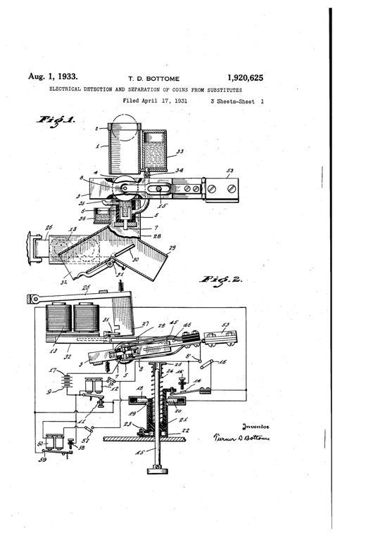
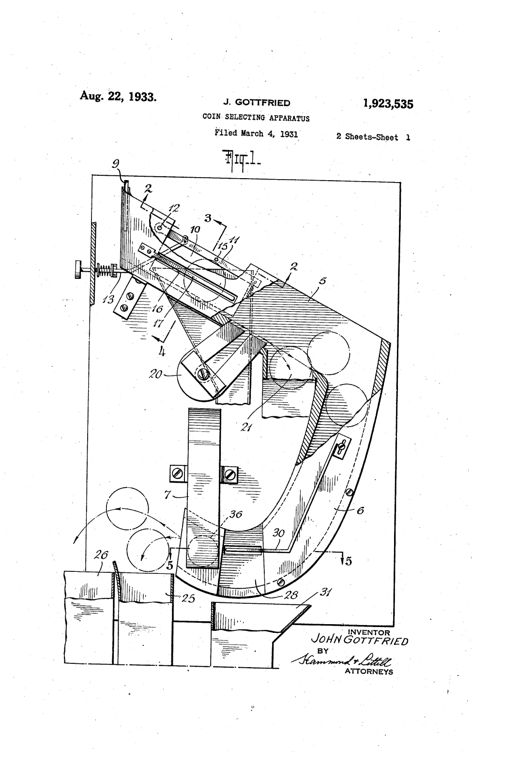
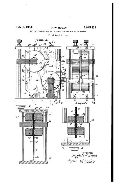
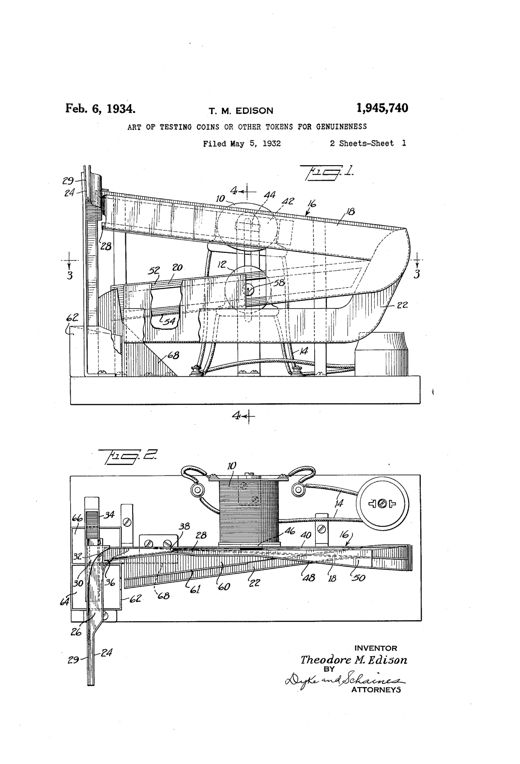
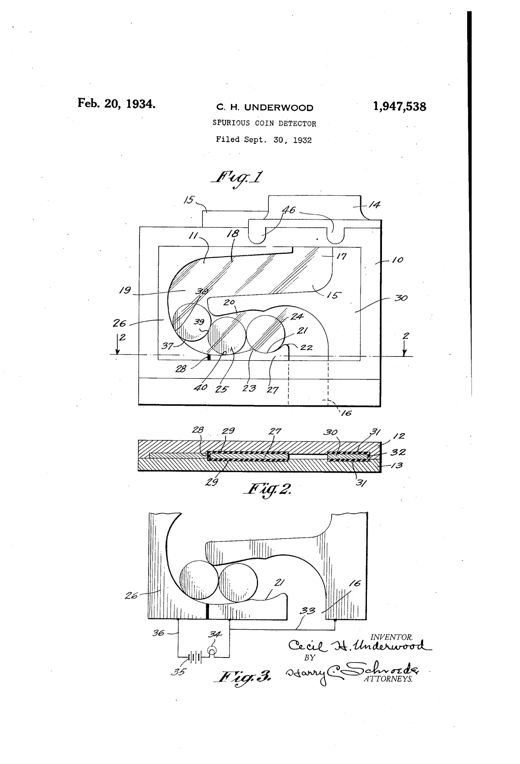
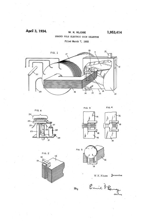
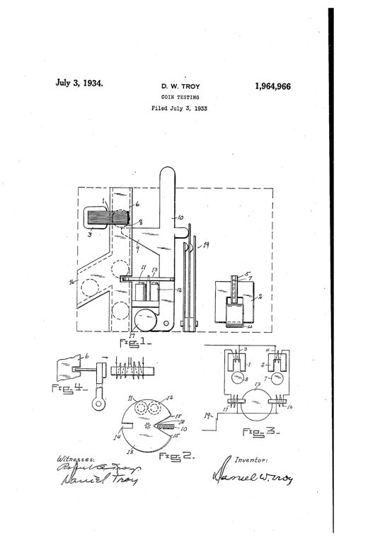
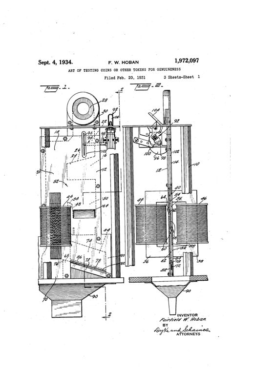
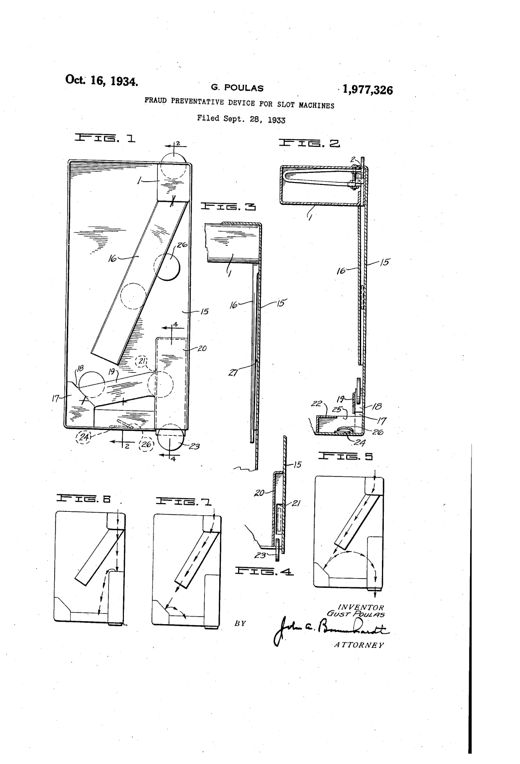
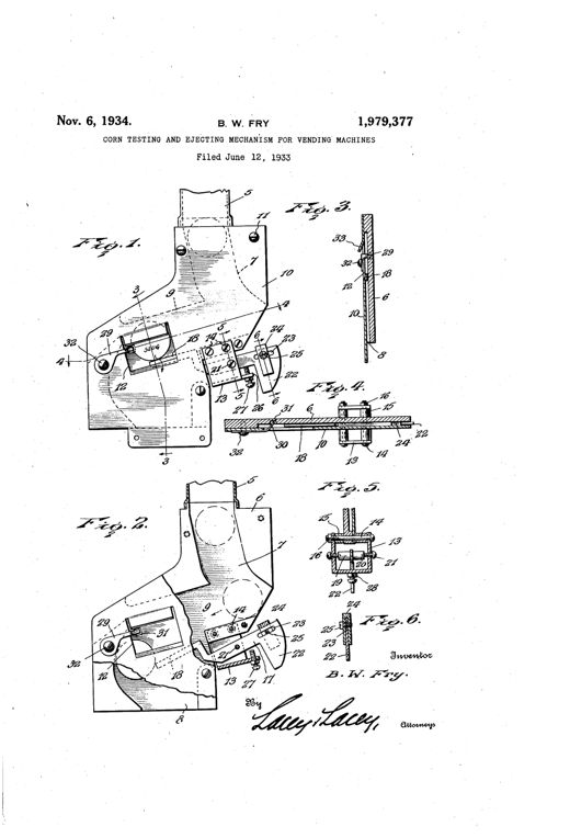
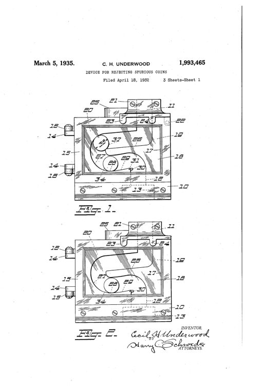
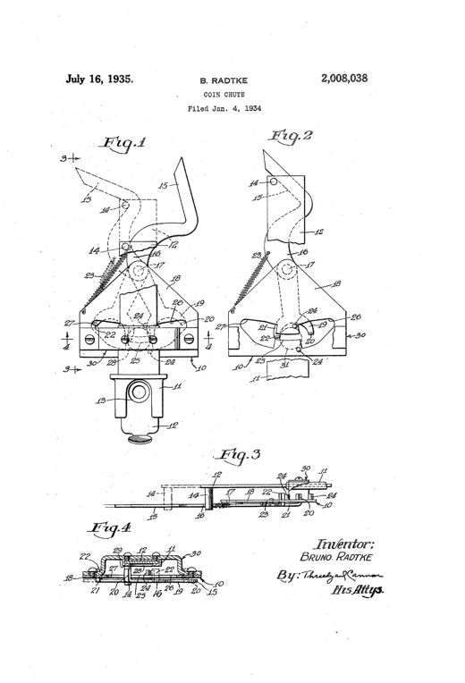
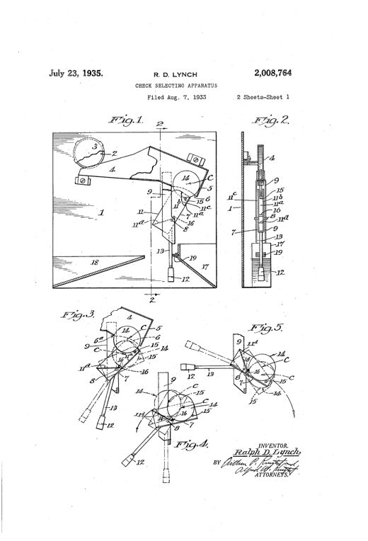
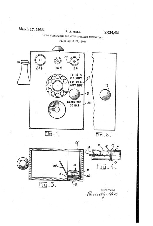
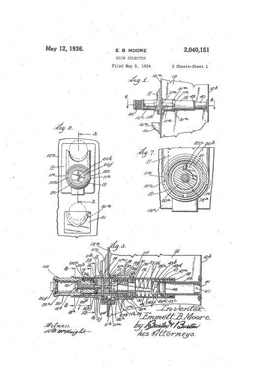
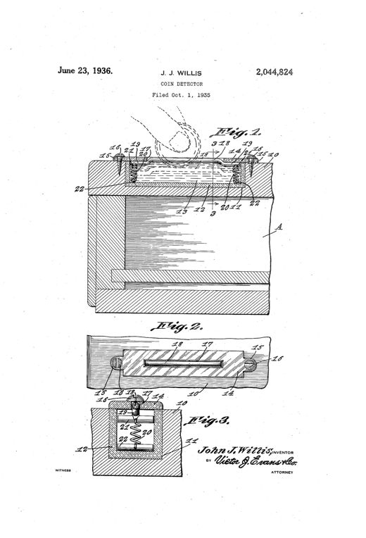
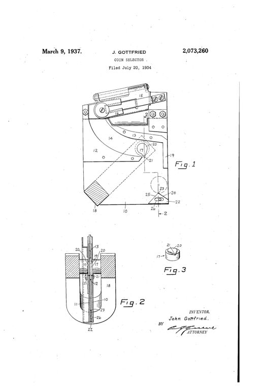
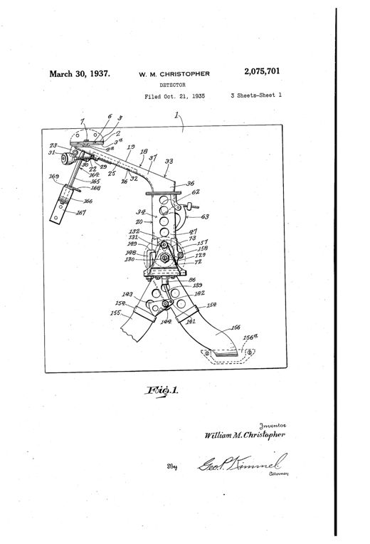
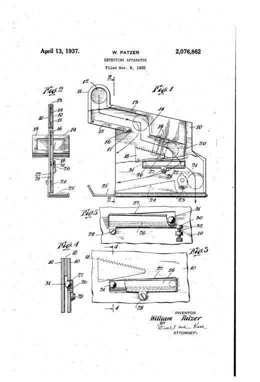
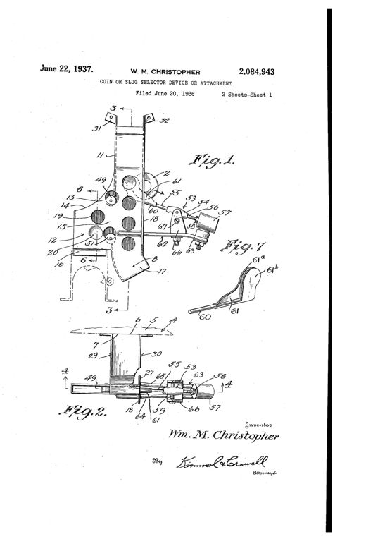
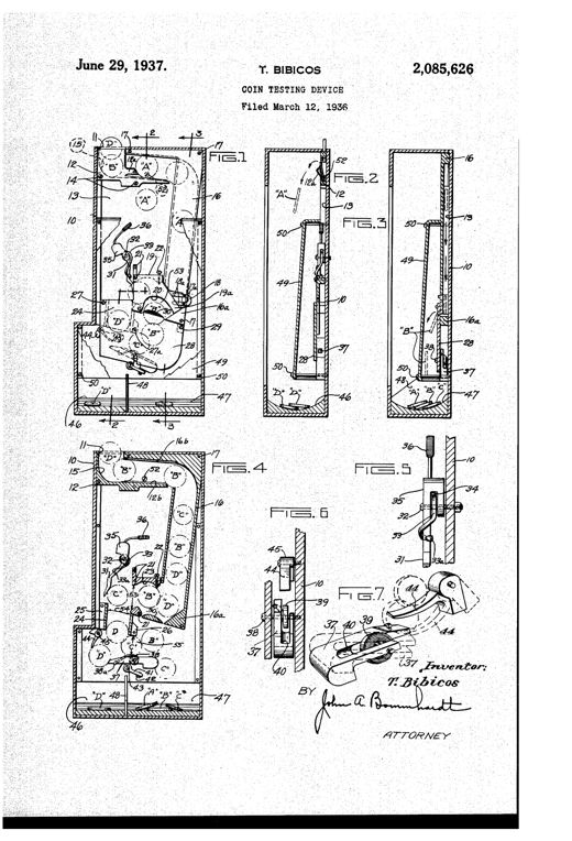
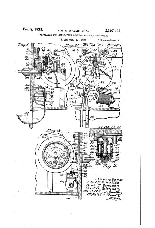
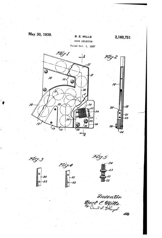
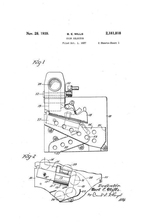
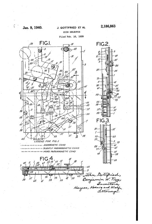
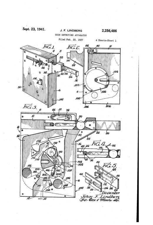
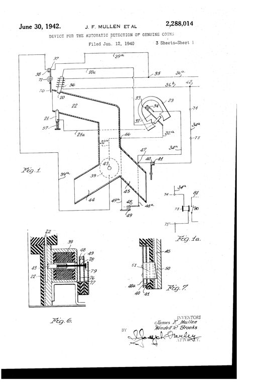
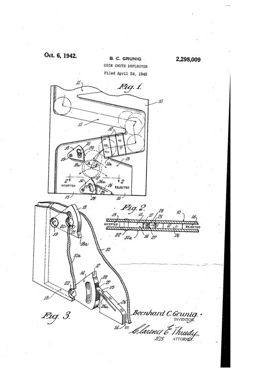
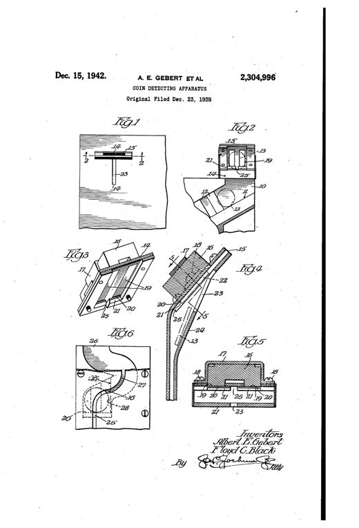
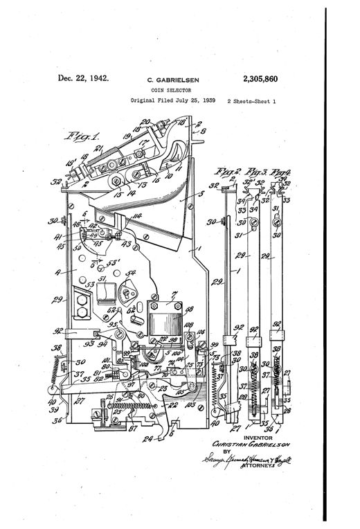
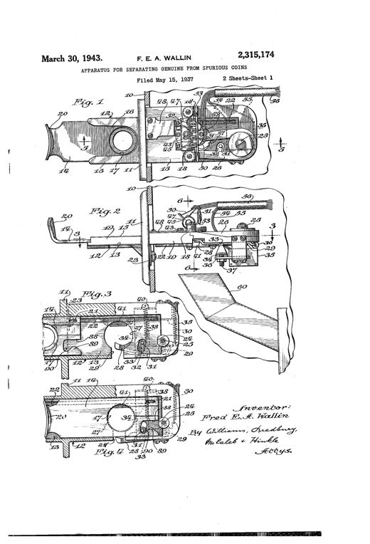
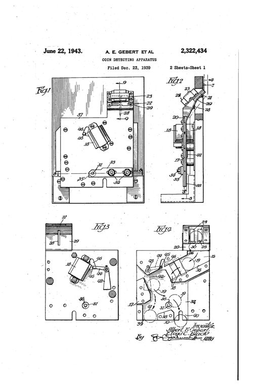
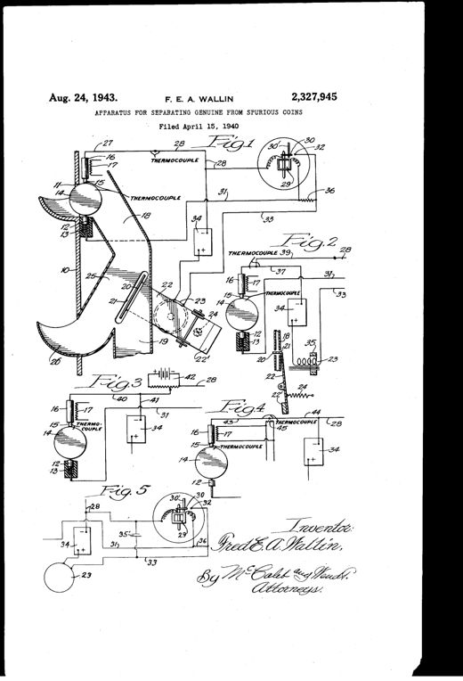
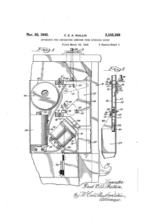
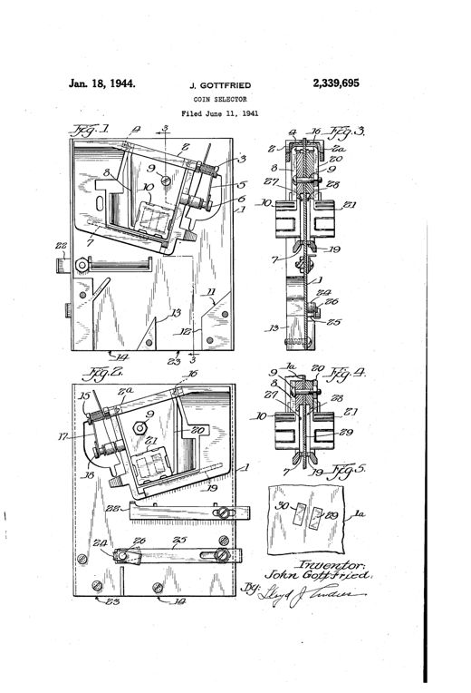
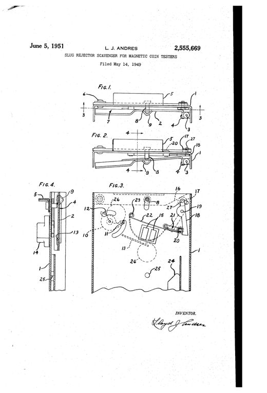
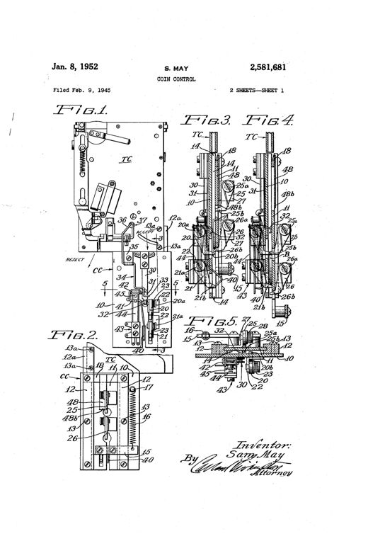
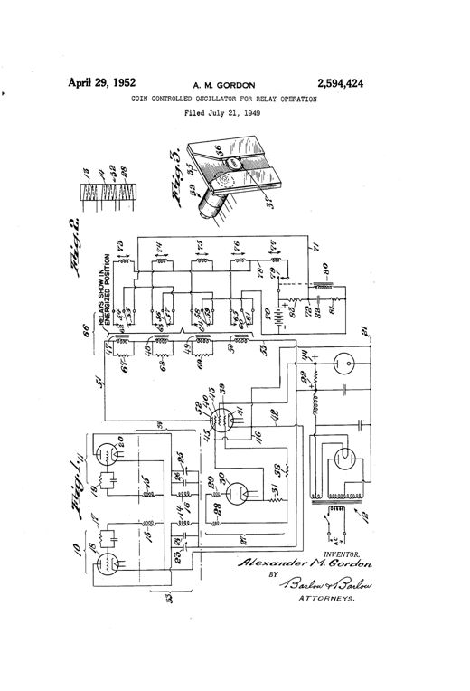
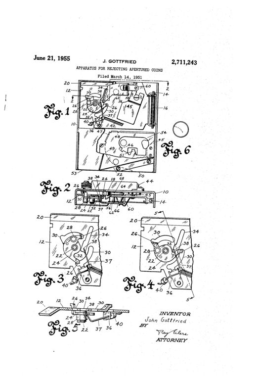
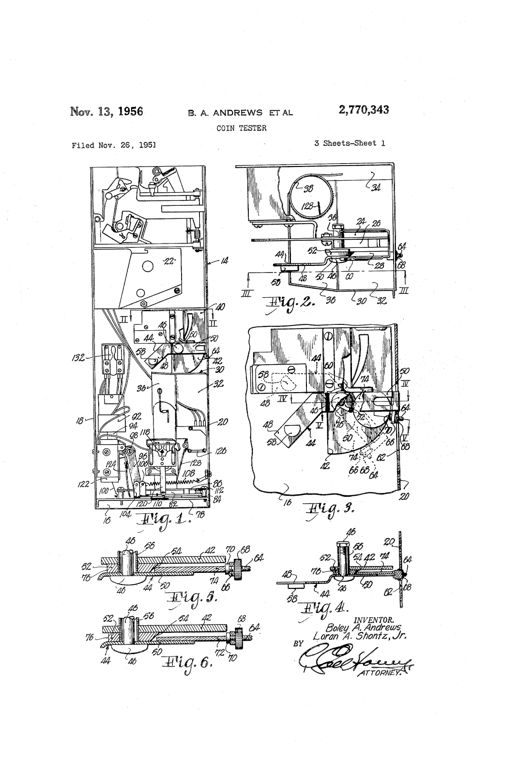
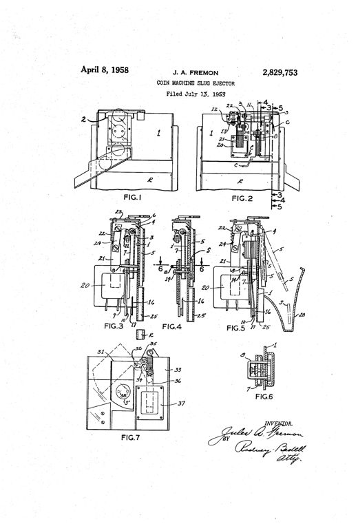
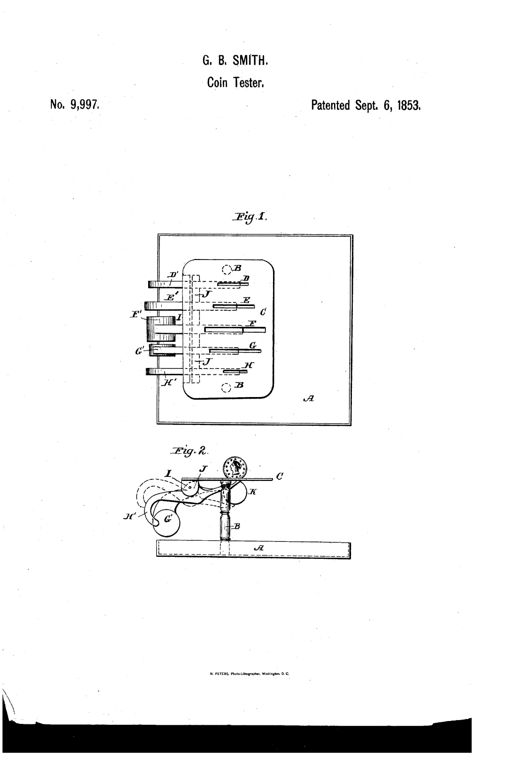
Patent drawing of an 1853 coin tester showing a rectangular gage plate with five graduated slots labeled D through H mounted on two posts above a base, with hidden dotted lines revealing internal pivoting levers and a rod I running beneath the plate; a second elevation view shows a single lever swinging a coin through the gage into a collection area below.COUNTERFEIT-COIN DETECTOR.Gideon B. Smith · September 6, 1853Technical patent drawing showing a long pivoting lever balance with multiple circular coin-sized cavities labeled E, F, G, H, L, and M along its length, mounted on a base with two pillars, alongside a small separate weight piece labeled J and K.BALANCE FOR DETECTING SPURIOUS COIN.John Allender · November 27, 1855Patent drawing of an 1857 coin balance showing a triangular graduated scale beam mounted on uprights with a lever, index pointer, and a plate with slots sized for different U.S. gold coin denominations.BALANCE FOR DETECTING COUNTERFEIT MONEYFerdinand J. Herpers · December 29, 1857Patent drawing showing a rectangular brass plate with a sliding scale marked for gold and silver coins, numbered diameter and thickness scales, and studs for testing coin weight and size, alongside a perspective view and cross-section.Coin-DetectorH. Maranville · February 14, 1860Patent drawing showing a metal counter plate with an inclined ramp leading into a pivoting, weighted spout flanked by upturned side gauges, plus top and inverted plan views labeled A and B showing the coin-sized openings.IMPROVEMENT IN COUNTERFEIT-COIN DETECTORS.William Painter · July 8, 1862Patent drawing showing a mechanical coin-counting apparatus with paired vertical guide channels, a central tilting balance plate, adjustable counterweights on threaded arms, and swinging vanes directing coins to separate receptacles, shown in top view and two cross-sectional views.IMPROVEMENT IN COIN-COUNTERSAron Bernstein · October 31, 1876A flat elongated metal plate resembling a paper-knife, bent at a right angle near the middle, with graduated slots labeled 10, 20, 25, and 50 near one end for testing coins of different denominations, shown in perspective and in two side views balancing a coin.IMPROVEMENT IN DETECTERS OF COUNTERFEIT COINJohn A. Thompson · February 27, 1877A patent drawing of an oblong cast-iron plate with two rounded end flanges each bearing a screw hole, and a central section with five parallel vertical slots of decreasing width labeled f, e, A, d, c, shown in both top view and cross-section.IMPROVEMENT IN DEVICES FOR DETECTING COUNTERFEIT COIN.Thomas J. Towsey · February 27, 1877Patent drawing showing a small tilting platform device with hooked gages that hold a fifty-cent coin in place, a knife-edge pivot beneath the platform, and a hidden balance-weight chamber, illustrated in level and tipped positions plus a top-down view of the coin secured by the gages.IMPROVEMENT IN COUNTERFEIT-COIN DETECTERSJohn Wiarda · March 20, 1877Six circular diagrams of a metal coin-testing disk showing concentric slots labeled a, c, and diameter markings 10, 25, and 50, with a pivoting knife-edge rod extending from the side, illustrating coins tilting up or down depending on weight.IMPROVEMENT IN COUNTERFEIT-COIN DETECTERSJohn W. Sutton · March 27, 1877Technical patent drawing showing a bent metal bar with flanges and paired clasping lugs used as a tipping balance to test coin weight, alongside cross-section and alternate frame views.IMPROVEMENT IN COUNTERFEIT-COIN DETECTERSJohn A. Thompson · April 3, 1877Technical patent drawing of a balance-lever coin detector showing a gage-arm A with cross-pieces B, D, and K on one side, an elongated weighted arm E on the other, pivoted atop a stand G, with additional detail views of the pivot mechanism and gage cross-section.IMPROVEMENT IN COIN-DETECTERSPatrick Doherty · June 19, 1877Patent drawing of a rectangular metal case with two longitudinal slots in its top plate, an internal curved balance bar visible in cross-section, a projecting handle arm, and guide bars beneath the slots, shown from side, top, and end views.IMPROVEMENT IN COUNTERFEIT-COIN DETECTERSEdward Kronenberg · September 25, 1877Patent drawing showing five figures of a pocket coin-testing device with labeled tubes (A), a weighted trip-lever (B), and casing (C), including top views and cross-sections, and a version mounted to a counter or money-drawer.IMPROVEMENT IN COUNTERFEIT-COIN DETECTERS.William H. Rice · October 16, 1877Patent drawing of a combined postal scale and counterfeit-coin detector showing a plan view (Fig. 1) with a large graduated disk marked for gold, silver, and postage rates, and a side cross-section (Fig. 2) showing the beam, counterweight box with shot, and coin pan.IMPROVEMENT IN POSTAL-SCALE AND COUNTERFEIT-COIN DETECTER.Harvey Maranville · April 30, 1878Patent drawing showing a rectangular cabinet divided into rows of labeled coin-detector cases (A) with inlet slots (a) for coin denominations, feeding into a series of adjacent boxes (D), plus a cross-sectional view revealing an internal tilting poise mechanism (B) inside a detector case.IMPROVEMENT IN COUNTERFEIT-COIN DETECTER AND COIN-RECEIVER.Samuel A. Field · May 14, 1878Patent drawing of a combined letter scale and coin detector showing a balance plate on standards, a sliding indexed weight, and a tray with nested circular coin depressions and matching slots.IMPROVEMENT IN COUNTERFEIT-COIN DETECTERSEdwin Street · October 22, 1878Patent drawing showing a beam scale with a slotted coin pan and vertical gauge plate, plus a secondary weighted beam marked for gold and silver coin denominations, alongside a base-mounted support stand.IMPROVEMENT IN COMBINED SCALE AND COIN-TESTERGeorge Hoag · June 3, 1879An elongated metal plate shown at an angle, marked 'GOLD' on one side with slots labeled for denominations 2½D, 5D, 10D, 20D, and 'SILVER' on the other side with slots labeled 10, 25, 50, and 1D, each slot tapering in width toward a central ridge running the length of the plate.Counterfeit-Coin Detecter.John A. Thompson · February 24, 1880Patent drawing of a 19th-century counterfeit coin detector showing a slotted measuring table above a coin box, with internal cylinders, floats, and trays for weighing coins using quicksilver.COUNTERFEIT-COIN DETECTOR.John B. Atwater · September 19, 1882Patent drawing of a folding pocket coin balance, showing a slotted metal plate pivoting on knife-edge bearings between two hinged standards mounted in a shallow box, with a small counterweight at one end and a removable supplemental plate with smaller slots for testing gold coins.COIN-TESTER.Merritt Clarke · March 6, 1883Patent drawing showing a boxed coin-detector mechanism with a pivoting weighted lever, coin pans, a scale-beam arm with a hook, and a coin-roll compressor with sliding guides, illustrated in five labeled figures.COIN-DETECTOREmil Bachmann · September 18, 1883A drawing of a balance-beam scale mounted on a pedestal, with one end holding a sliding graduated weight and coin cups sized for gold coins with slots for testing, and the other end fitted with a wire yoke and springs with grapple hooks for holding letters, alongside a separate plan view showing five circular coin-testing cups linked along a bar.COMBINED LETTER-SCALE AND COIN-TESTER.Edward C. Purnelle · January 29, 1884Patent drawing of a Victorian coin-operated strength testing machine with a round dial gauge on top, a pillar with handles for pulling, and a sliding seat with foot rests mounted on a pedestal base.COIN-OPERATED MACHINE FOR TESTING MUSCULAR POWER.Percival Everitt · November 29, 1887Patent drawing of a tall wooden coin-operated height-measuring cabinet showing a sliding graduated bar, a coin chute mechanism, and a hinged pointer plate with associated levers and brackets.COIN-CONTROLLED HEIGHT-MEASURING MACHINE.Charles R. Williams · May 29, 1888Patent drawing of a coin-controlled weighing scale showing a circular graduated dial (Fig. 1) with a pivoted covering bar, gears, and internal mechanism including a coin chute, coin-receiver, tripping arms, and rack-and-pinion assembly housed within a wooden case.COIN-CONTROLLED WEIGHING-SCALEGeorge P. Hill and Albert L. Washburn · September 11, 1888Patent drawing showing eight figures of a coin-slot mechanism with spring-loaded pivoting catches, a bridge and tongue guide, and a hooked washer-diverting chute, labeled with lowercase letters a through n.APPARATUS FOR PREVENTING FRAUD IN VENDING-MACHINESEdward Phipps Appleyard and James Johnson · July 23, 1889Patent drawing sheets showing multiple mechanical diagrams of a coin-chute with pivoted gripping-arms, magnets, springs, and sliding stops designed to detect and block counterfeit lead or iron coin slugs.COIN FREED OR ACTUATED MACHINEAnthony Harris · August 12, 1890Patent drawing of a cylindrical coin-operated strength-testing machine showing internal gearing, a rack bar, friction wheels, a coin chute, and a foot-piece lever connected by rods to the mechanism.COIN-CONTROLLED STRENGTH-TESTING MACHINE.Alfred W. Roovers and Alexander H. Roovers · August 19, 1890Patent drawing showing a tall cylindrical vending-machine casing with an internal zigzag coin race suspended on a spring and shaft, alongside detail views of the zigzag race sections, a plan view of the rotating coin chute, and a side elevation of an alternative lever-and-weight support mechanism.MACHINE FOR THE ASSORTMENT OF COINS.Henry C. Hart · October 20, 1891Patent line drawing showing a tall coin-operated cabinet mechanism (Fig. 1) with a hinged coin slide, magnet, push-handle, camera and dash-pan assembly, alongside a detail front view of the money-box (Fig. 3) and a partial side view (Fig. 2) of the slide linkage.COIN FREED OR ACTUATED MACHINE.Helen Alicia Burt · March 29, 1892Mechanical drawing of a coin-controlled phonograph mechanism showing a vertical coin tube with numbered levers, a hinged door, springs, and a handle arm for testing deposited coins.COIN-CONTROLLED DEVICE FOR PHONOGRAPHS.John F. Ott · July 12, 1892Patent drawing of a tall wooden vending-machine cabinet front and side views, with an enlarged mechanical coin-tester assembly showing hinged plates, springs, pins, and a coin diagram labeled with letters D, E, F, m, n, o, p.COIN CONVEYER AND TESTER FOR AUTOMATIC VENDING-MACHINES.John H. Volkmann · September 27, 1892Patent drawing showing a tall rectangular cabinet with internal gears, a tilting coin tray, ratchet wheel, pawl arm, and coin chutes labeled with reference letters, alongside detail views of a sliding coin plate and tray locking mechanism.COIN OR CHECK CONTROLLED DELIVERY APPARATUSJohn W. Smallwood · January 16, 1894Patent drawing showing six figures of a coin-slot protection mechanism with a reciprocating slide, spring-loaded ejector, magnet, and coin chute, plus hand-operated views of a coin being inserted.MEANS FOR PROTECTING RECEIVING-OPENINGS OF COIN-CONTROLLED MACHINES.Almy Le Grand Peirce · March 20, 1894A patent drawing of a small house-shaped mechanical toy bank with an arched roof, barred windows, and a coin slot, alongside detailed mechanical diagrams of its internal music-box gears, coin chute, locking latch, and stop-wheel components.COIN-CONTROLLED MUSICAL TOY BANK.Henry W. Porter · October 30, 1894Line drawing of an upright player piano cabinet with a coin slot mechanism exposed beneath the keyboard, alongside detailed close-up diagrams of the coin slide, circuit closer, contact bar on perforated paper, and wiring schematic connecting a battery, motor, and electromagnet.COIN-CONTROLLED ELECTRICAL MUSICAL INSTRUMENT.Philip Wuest, Jr. · January 1, 1895Patent drawing of a coin-introducing device showing four figures: a top plan view of a square plate with a central rotating disk and crank, a side sectional view with a chute below, a plan view of the middle plate with circular openings labeled b, c, and d, and a bottom plate view with three circular openings labeled for cent, nickel coin, and a central opening.COIN-INTRODUCING DEVICE FOR COIN-CONTROLLED VENDING-MACHINES.Willard H. Gilman · October 8, 1895Patent drawing of a coin-operated telephone apparatus showing a hollow post rising from a sounding-case containing a coin slot and bell, topped by a pivoting transmitter case with a curved telescoping sound tube, illustrated in two configurations labeled Fig. 1 and Fig. 2.TELEPHONE.Samuel Alexander · November 5, 1895Patent drawing of a slender pencil-shaped metal holder with a pointed pencil tip at one end and a rounded eraser cap at the other, showing an extendable pivoting arm and a sliding notched sleeve marked with coin denomination numbers along its graduated scale.COMBINED PENCIL-HOLDER, ERASER-HOLDER, AND COIN-TESTER.Rudolph Wm. Riess · November 12, 1895Patent drawing of a mechanical coin detector showing front and interior views with a row of coins in a horizontal channel, a vertical entry chute, a spring-loaded slide with finger hole, and small cross-section detail figures at the bottom of the page.COIN-DETECTOR FOR COIN-CONTROLLED APPARATUS.Arthur L. Pratt · May 26, 1896Patent drawing of a 19th-century coin detector showing an angled chute with a pivoted magnet, lever, and push-off mechanism for trapping and ejecting false iron or steel coins from a vending machine.COIN-DETECTOR FOR AUTOMATIC VENDING-MACHINES.Alexander Jaeger · July 28, 1896Patent drawing of a clock-like bonus-determining device with a large numbered dial on a pedestal base flanked by matchbox holders, showing internal gears, a coin-rotated spider wheel, and a rocking valve mechanism in cross-section views.BONUS-DETERMINING DEVICE.Judson H. Drobisch · April 6, 1897Patent drawing of a mechanical coin-tester showing a hinged plate assembly with a pivoted magnet, coin track, and washer-catcher arm mounted inside a tall vending-machine cabinet.VENDING-MACHINEJohn H. Volkmann · February 8, 1898Patent drawing of a wall-mounted telephone pay station showing the magneto signal box, battery box, telephone receiver, bell, and an attached coin toll-box with internal chute and signal mechanism, alongside detailed sectional views of the toll-box interior and transmitter arm.COIN-CONTROLLED TELEPHONE PAY-STATION.William Gray · February 8, 1898Patent drawing of a coin-tester mechanism showing an inclined housing with a slotted plate, pivoted magnet, and hooked washer-catcher arm inside a metal frame, illustrated from multiple side and sectional views.COIN-TESTER FOR COIN-CONTROLLED APPARATUS.John H. Volkmann · October 4, 1898Exploded mechanical drawings of a metal coin-detector case with slotted chutes, pivoting studded levers, a push-bar handle, and a glass-covered display opening showing three coin discs stacked in the chute.BOGUS-COIN DETECTOR FOR COIN-OPERATED VENDING-MACHINESMortimer B. Mills · November 8, 1898Patent drawing showing a coin-detector ejector mechanism with a pivoted horseshoe magnet, bent rod, incline bar, and push-off plate mounted on a bracket, with five labeled cross-sectional figures illustrating the mechanism in normal and coin-actuated positions.EJECTOR FOR COIN-DETECTORS FOR MONEY-CONTROLLED MACHINES.Otto Jaeger and Alexander Jaeger · December 12, 1899Patent drawing showing five figures of a mechanical coin-guard device with a vertical coin chute, a U-shaped pivoting gate with arms fitting into grooves, a leaf-spring, and a rotating arbor with releasing lever, all numbered with reference numerals like 1 through 21.COIN-GUARD OR CONTROLLING DEVICE FOR COIN-OPERATED MACHINES.Robert Fred. Tochtermann · December 12, 1899Patent drawing of a countertop coin-detector showing a boxed housing with three coin slots and internal balance beams mounted on a turned pedestal base, plus detail views of individual pivoting coin-rest balances and their adjustable weighted arms.COIN-DETECTORThomas I. Porter · March 13, 1900Perspective cutaway drawing of a wooden cabinet cigar vending machine showing an internal spring-driven disk with stepped peripheral walls, tubular cigar-elevating plungers, a coin slot leading to an electrolytic cell, a solenoid and clutch mechanism, and a row of coin cups with lobed disks for dispensing change, alongside a hand crank on the side wall.COIN-CONTROLLED CIGAR-VENDING MACHINEOtto Beese · April 16, 1901Technical patent drawing showing a complex mechanical coin-testing apparatus with multiple gears, levers, springs, and pivoting arms arranged within a rectangular housing frame, including a knob-topped shaft and numbered reference points identifying individual components.APPARATUS FOR DISTINGUISHING GENUINE FROM SPURIOUS COINSJohn E. Evard · December 17, 1901Patent drawing of a vertical coin-chute mechanism showing a slidable coin-receiver with springs, a thrust-rod and handle at top, and a pivoted lever and follower-rod assembly that releases the coin only when the receiver is fully inserted, with a detailed washer-blocking cross-section and a coin depicted lodged in the receiver.FRAUD-PREVENTING DEVICE FOR COIN-CONTROLLED APPARATUSOscar E. Sorg · January 7, 1902Patent drawing sheets showing a round coin-operated mechanism with a rotating coin-carrying disk, detector lever, springs, and pawls mounted between two plates, plus detailed cross-sections of the lever and coin slot.COIN-CONTROLLED MECHANISM.Alvah C. Roebuck and Frank McMillan · February 11, 1902Patent drawing of an antique penny weighing scale showing the circular head with hidden dial, coin slot, pivoting shutter arm with counterweight, and a radial tripper wheel, mounted atop a tall pedestal base.AUTOMATIC WEIGHING-MACHINE.Frederick N. Magee · July 7, 1903Patent drawing showing three figures of a coin-detective device: a two-part block with a spring-loaded plunger, knob, rod, coil spring, and pegs that catch washers while allowing coins to pass through separate discharge outlets.COIN-DETECTIVE.George W. Brown · August 11, 1903Patent drawing of a cabinet-style coin-operated lung testing machine showing a tall glowing lamp array, an internal air cylinder and piston with a coin chute and switch mechanism below, plus a detailed diagram of the wiring connections for the lamps.COIN-CONTROLLED TESTING-MACHINE.Santley M. Taylor · October 13, 1903Patent drawing of a mechanical coin detector showing a winding coin chute, spaced coin-rests, a pointed sliding bar, an electromagnet, and coin pockets with 'V CENTS' coins visible in the casing.COIN-DETECTORFrederick G. Hartell · April 19, 1904Patent line drawing of a tall vending machine cabinet with an internal coin guideway mechanism, pivoted castings with hooked fingers, chutes, and an ejector rod, shown in section and detail views.FRAUD-PREVENTIVE FOR COIN-CONTROLLED MACHINESMaurice Hofheimer · June 27, 1905Patent drawing of a mechanical coin detector showing an inclined chute with a magnet and pivoted retarding arm feeding into a curved segmental chute, which delivers coins onto a spring-loaded pivoting tilting bar mounted inside a vending machine case.COIN-DETECTOR FOR VENDING-MACHINES.Claude Bigelow · July 11, 1905Patent drawing of a coin-tester showing two upright posts holding a crank-operated shaft with paired slotted heads that grip and test a coin between them, mounted on a rectangular wooden base with a spring and adjusting screw beneath.COIN-TESTER FOR SLOT-MACHINES.Morgan D. Sadtler · July 31, 1906Patent drawing of a mechanical gum vending machine cabinet showing an internal coin chute, pivoted testing gate with counterweight, discharging arm with numbered fingers, and separate compartments for genuine coins and rejected slugs.COIN-CONTROLLED SLOT OR VENDING MACHINE AND COIN-TESTING MECHANISM THEREFOR.Louis J. Disser · November 13, 1906Patent drawing sheets showing a mechanical coin-slot fraud preventive device with a hinged plate, adjustable stop, spring-loaded roller, handle rod, and return chute, illustrated across twelve labeled figures with numbered parts.FRAUD-PREVENTIVE DEVICE FOR COIN MECHANISMS.John Fritsche · April 30, 1907Patent drawing of a telephone coin box mechanism showing coin slots, chutes with magnets, a crank-operated shaft with kick-off fingers, and a weighted lever striking a bell to signal valid coin deposit.COIN-CONTROLLED MECHANISM FOR TELEPHONE-BOXES AND THE LIKE.Francis X. Bee · March 10, 1908Patent drawing showing the interior of a vending machine casing with a coin slot, an inclined chute leading to a pivoted dumping table with a hooked gripper arm, and separate accepting and rejecting chutes below, along with detail views of the gripper and shedder mechanism.COIN-SORTING MECHANISMCharles E. Dellenbarger · June 30, 1908Patent drawing of a rectangular vending-machine coin box housing two parallel slotted shafts with gear wheels, springs, set screws, and diverging chutes, shown in six views labeled Fig. 1 through Fig. 6.SPURIOUS-COIN DETECTOR FOR VENDING-MACHINES.Leslie A. Vandiver · May 4, 1909Technical patent drawing of a cylindrical coin selector casing with an internal plunger, spring-loaded disk, pivoting valve plate, gauge rods, and an electromagnet assembly used to test and sort coins in a vending machine.COIN-SELECTORGeorge C. Reith and George F. Flade · September 17, 1912Patent drawing of a coin chute mechanism with a coin (11) resting against a pivoted stop pin, a prism lens (13) mounted at an angled opening to magnify the coin's image, and a rock shaft, spring, and detent arm assembly (32-42) that releases the coin when a new one is deposited.SLUG-DETECTING DEVICE FOR COIN-CONTROLLED MACHINES.Frank Hedley and James S. Doyle · October 12, 1926Two mechanical drawings of a vending machine coin mechanism showing a vertical coin tube with a counterbalanced testing lever, rejection spout, and a rotating pocketed release disc connected to a handle and discharge tube.COIN-RECEIVING MECHANISM FOR VENDING MACHINESRufus B. Sherburne, Leon G. Sherburne, and Martin Hansen · May 17, 1927Patent drawing sheets showing exploded mechanical views of a coin-controlled dispensing machine with an inclined disk passage, gauge plates, pivoted deflecting arms, a magnet, and a reciprocating coin carrier tray, labeled with numbered reference lines.COIN-CONTROLLED MECHANISMArthur H. Du Grenier · February 12, 1929Cutaway front elevation of a mechanical fare box showing a stack of coin selector slides, ejector bars, springs, and a crank-driven operating head mounted on an internal partition, with a coin hopper wheel at lower left.COIN-ASSORTING MECHANISM FOR FARE BOXESFrank G. Murray · June 25, 1929Exploded and assembled mechanical drawings of a metal coin chute assembly showing separate side walls, an intermediate wall with an opening, a horseshoe magnet, and a toothed rotating detector wheel that sorts coins from slugs into two discharge paths.COIN DETECTORBenjamin L. Fry · October 22, 1929Patent drawing showing a coin-testing chute with an electromagnet coil, lever-operated slow-opening switch, and circuit diagram, plus a second bench-top device with an adjustable coin-support arm and graduated scale for dimes through dollars.METHOD OF AND MEANS FOR TESTING COINSFrederic H. Brinkerhoff · May 27, 1930Patent drawing of a coin depository casing showing front slots for nickels, dimes, and quarters, an internal spring-loaded plunger with sized coin pockets, a notched gauge bar, and U-shaped resilient wire guard fingers designed to reject slugs and improperly sized coins before they reach the delivery chutes.COIN DEPOSITORYHarry Walker · December 30, 1930Cross-sectional patent drawing of a coin-selecting mechanism showing an inclined entrance slot leading to a vertical main slot with a pivoting anvil, a curved branch slot, a spring-loaded latch, and a lower tray for rejected coins, with a second smaller cutaway view below showing the anvil assembly.COIN-SELECTING DEVICEJoy V. Wigle and John E. Reece · March 31, 1931Two patent drawing sheets show a rectangular metal coin-detector housing with internal chutes, a curved magnet track, a pivoting counterweighted pallet with hooked fingers, and cross-section details of the coin passage and rejection exit mechanism.REJECTION MEANS FOR PERFORATED COINSJames E. Olvis · September 1, 1931Patent drawing of a mechanical coin tester showing a sloped coin deposit chute feeding a spring-supported runway with vertical guides, adjustable pivot blocks, and switch fingers that divert coins of improper weight into a separate reject conduit.COIN TESTING DEVICEClifton W. Nixon · September 1, 1931Patent drawing sheet showing an arch-shaped coin-mechanism casing with a star-shaped coin slot handle, an internal disk-like coin carrier with locking levers and a pivoted horseshoe magnet, and cross-sectional side views labeling numbered parts such as the shaft, magnet support, spring, and locking pin.CHECK CONTROLLED MECHANISMArthur H. Du Grenier · December 29, 1931Mechanical schematic of a vending-machine coin selector showing gears, pivoted levers, a weighted balancing arm, and chutes for accepting or returning coins.AUTOMATIC FRAUD PREVENTIVE MEANS FOR CHECK CONTROLLED APPARATUSAaron A. Knee · October 11, 1932Patent drawing of a coin-testing apparatus showing a boxy casing with an internal magnetic core, coil, spring-loaded roller, and a hinged armature with coin passages, alongside a perspective view of the finished enclosed device with a coin slot on top.ART OF TESTING COINS OR OTHER TOKENS FOR GENUINENESSFairfield W. Hoban · December 6, 1932Mechanical drawing of a coin detector housing showing a zigzag arrangement of inclined metal anvils, vertical guide strips, an overhead deflecting anvil, a magnet, and two discharge chutes leading to a coin-controlled device and a return cup, with a side cross-section below labeled Fig. 2.SPURIOUS COIN DETECTOR AND EJECTOREmil de Ryss · February 7, 1933Patent drawing showing a coin slot mechanism with a support plate, sliding coin-carrying strip with handle, housing with lateral flanges, ridges and studs for anti-fraud protection, and a magnet-equipped trigger arm, illustrated in seven labeled figures including top, side, and cross-sectional views.COIN CONTROLLED DEVICELouis M. Hall · February 14, 1933Patent drawing of a telephone pay-station coin box showing an inclined coin slot with a pivoting weighted lever that either lets a genuine quarter pass or tips to eject a lighter counterfeit coin through a side discharge opening into a separate reject chute.SPURIOUS COIN SEPARATOREdward P. Donnellan · February 28, 1933Patent drawing showing an inclined coin guide tube feeding into a tiltable weighing scale with adjustable counterweight, guide strips, and separate receiving and return channels, with two smaller cross-section figures below detailing the hanger yoke and weight assembly.FRAUD PREVENTIVE DEVICEHobart J. Halsted · April 25, 1933Patent drawing showing a vertical coin chute mechanism with labeled magnets, pivots, and diverging passages, plus side-view and cross-sectional details of the coin runway construction.COIN SELECTING APPARATUSJohn Gottfried · May 2, 1933Patent drawing showing a long sliding guide plate and strip mechanism with coin apertures, spring trigger, magnet, and abutment arm, illustrated in eight cross-sectional and plan views labeled Fig. 1 through Fig. 8.COIN CONTROLLED DEVICELouis M. Hall · May 16, 1933A schematic patent drawing of a Wheatstone bridge coin-testing circuit with springs, pivots, a galvanometer, contact switches, a solenoid coil, and a battery, alongside a smaller detail view labeled Fig. 2 showing a modified contact arrangement.COIN CHECKING MEANS AND METHODSamuel D. Polsen and Sven Herbert Nelson · May 23, 1933Patent drawing showing seven mechanical diagrams of a coin chute device with a pivoted bell crank, spring, and pin mechanism that sorts true coins from spurious or lightweight coins into separate collection and rejection passages.SPURIOUS COIN DETECTORCharles A. Fowler · June 6, 1933Patent drawing of a mechanical coin-testing apparatus showing a check receiving chute, electrolytic cell with coin as anode, spring contacts, an electromagnet-actuated deflector pin, and a wiring diagram connecting batteries, relays, and coil solenoids.ELECTRICAL DETECTION AND SEPARATION OF COINS FROM SUBSTITUTESTurner D. Bottome · August 1, 1933Patent drawing of a coin-selecting apparatus showing an inclined upper chute with a movable top rail and ejecting spring leading into a vertical J-shaped chute flanked by magnet pole pieces, with numbered parts and a lower coin return tray.COIN SELECTING APPARATUSJohn Gottfried · August 22, 1933Patent drawing showing a boxy coin-testing apparatus with insulated vertical panels, wound electromagnetic coils on laminated cores forming gaps for a coin chute, a rocker arm and stop pin mechanism, and two lateral outlets for accepted and rejected coins, shown in front elevation, side elevation, and two cross-sections.ART OF TESTING COINS OR OTHER TOKENS FOR GENUINENESSFairfield W. Hoban · February 6, 1934Patent drawing of an inclined chute apparatus with two electromagnets positioned along the coin path, showing a coin rolling on edge past the magnets and being deflected into separate collection compartments based on its metal composition.ART OF TESTING COINS OR OTHER TOKENS FOR GENUINENESSTheodore M. Edison · February 6, 1934Patent drawing showing a rectangular coin-detector housing with a winding internal coin path, circular coin positions, and a wiring diagram with a battery and lamp for signalling a fake coin.SPURIOUS COIN DETECTORCecil H. Underwood · February 20, 1934Patent drawing of a coin selector showing a laminated electromagnet with shading coils, a coin chute assembly labeled with numbered parts, and a separate time-switch mechanism with a mercury switch and dashpot piston.SHADED POLE ELECTRIC COIN SELECTORWalter Karl Klose · April 3, 1934Patent drawing showing a coin-testing device with two transformer coils, a coin chute, a lever-operated detent, and a rotatable disc mechanism for routing accepted or rejected coins, alongside a circuit diagram of the electromagnetic testing system.COIN TESTINGDaniel W. Troy · July 3, 1934Patent drawing of a vertical coin-testing chute assembly showing two stacked electromagnetic coils with laminated cores forming gaps through which a coin drops, flanked by insulating side panels with numbered passages, inclines, and outlet openings for sorting genuine coins from counterfeit slugs.ART OF TESTING COINS OR OTHER TOKENS FOR GENUINENESSFairfield W. Hoban · September 4, 1934Patent drawing of a rectangular slot-machine coin box showing an inclined coin slide leading to a metallic bouncing block, with side sections illustrating the paths taken by genuine coins versus thin or soft metal slugs into a slug pocket.FRAUD PREVENTATIVE DEVICE FOR SLOT MACHINESGust Poulas · October 16, 1934Patent drawing of a coin testing and ejecting mechanism showing an angular coin chute casting with a weighing lever, counterweight bracket, resilient spring lip, and discharge opening, illustrated in six labeled figures with a signature reading B.W. Fry.COIN TESTING AND EJECTING MECHANISM FOR VENDING MACHINESBenjamin W. Fry · November 6, 1934Patent drawing of a rectangular glass-windowed coin detector casing with a circuitous internal track, showing pivoted selector wheels, a counterweighted trap door, and coin recesses labeled with numbered reference lines.DEVICE FOR REJECTING SPURIOUS COINSCecil H. Underwood · March 5, 1935Line drawing of a mechanical coin chute assembly showing a sliding coin tray, a triangular pivoting ejector arm with a coil spring, a shelf with numbered stop pins and discharge slots, and side/cross-section views labeled Fig. 1 through Fig. 4.COIN CHUTEBruno Radtke · July 16, 1935Patent drawing showing a coin chute leading to a pivoted balance arm mechanism with weighted counterlevers that tips one way to accept or another way to reject a check based on its weight.CHECK SELECTING APPARATUSRalph D. Lynch · July 23, 1935Patent drawing of a coin-operated payphone front panel showing coin slots labeled 25¢, 10¢, and 5¢, a rotary dial, warning text about felony slug use, and internal mechanical diagrams of a spring-loaded plunger device for detecting slugs.SLUG ELIMINATOR FOR COIN OPERATED MECHANISMSRussell J. Hall · March 17, 1936Patent drawing of a cylindrical coin selector mechanism with a tubular transfer member, escutcheon plate, calibrating pins, springs, levers, and an adjustable knob, shown in side elevation, cross-section, and multiple transverse sectional views.COIN SELECTOREmmett B. Moore · May 12, 1936Patent drawing showing a rectangular coin-testing well embedded in a cash register counter, with a slotted cover plate, spring-loaded closure bar, and cross-section detailing internal springs and solution chamber.COIN DETECTORJohn J. Willis · June 23, 1936Patent drawing of a coin selector mechanism showing a side elevation with coin chute, magnet pole pieces with pointed projections, and a pivoted separator edge, plus a cross-section and enlarged pole piece detail.COIN SELECTORJohn Gottfried · March 9, 1937Patent drawing of a mechanical coin detector showing an angled coin slide feeding into a chute assembly with pivoted weighing pan, counterweighted lever, rotating shaft structures with clutch pins, and branching discharge chutes for coins versus slugs.DETECTORWilliam M. Christopher · March 30, 1937Patent drawing showing a side-view mechanical coin detector with an inclined chute, bar magnet, serrated edge member, and ball-in-groove anti-tilt runway, along with cross-sectional and enlarged detail views of the coin-guiding plates and pivoted track member.DETECTING APPARATUSWilliam Patzer · April 13, 1937Patent drawing of a mechanical coin and slug selector showing a vertical housing with internal chutes, rollers, and a counter-balanced pivoting arm with adjustable stop screw that sorts coins from light and heavy slugs into separate discharge paths.COIN OR SLUG SELECTOR DEVICE OR ATTACHMENTWilliam M. Christopher · June 22, 1937Patent drawing of a coin testing device showing a vertical casing with internal chutes labeled A, B, C, D, magnets, pivoted gates, springs, and compartments for sorting coins and slugs by size and weight.COIN TESTING DEVICETheodore Bibicos · June 29, 1937Patent drawing showing a coin-testing mechanism with a rotating carriage, heated contact stud, electromagnet-actuated gate, and two coin chutes, plus accompanying wiring diagrams with a relay, transformer, and vacuum tubes.APPARATUS FOR SEPARATING GENUINE AND SPURIOUS COINSFred E. A. Wallin · February 8, 1938Patent drawing of a mechanical coin selector showing an angled coin chute, a stack of thin spaced steel plates forming a rebound surface with knife edges, mounting screws, spacer blocks, and a side elevation of the assembled unit with labeled parts 10 through 34.COIN SELECTORBert E. Mills · May 30, 1939Patent drawing of a coin selector mechanism showing a vertical base plate with an inclined coin chute, a horseshoe magnet with upward-projecting poles, a pivoted kicker arm, adjustable screws and bridge block, and multiple discharge passages for sorting coins by magnetic response.COIN SELECTORBert E. Mills · November 28, 1939Patent drawing of a coin selector showing a rectangular base plate with a coin chute at upper left, a horseshoe magnet mounted mid-plate, multiple dashed trajectory lines labeled with letters showing coin paths, numbered screws and projections, plus three cross-sectional side views (Figs. 2-4) and a top-down sectional view (Fig. 4) of the layered plates and outlet channels.COIN SELECTORJohn Gottfried and Benjamin W. Fry · January 9, 1940Exploded and sectioned patent drawings of a rectangular coin-detector housing showing sliding gauge levers, a knurled sizing disc, a pivoted weight-measuring pendulum with jaws, and numerous numbered pins, screws, and channels for sorting coins from slugs.COIN DETECTING APPARATUSJohn F. Lindberg · September 23, 1941Patent drawing showing a coin chute with heated and cold electrode contacts, a horseshoe-shaped galvanometer relay, a solenoid with movable core, and branching chutes leading to a rejector path and a genuine-coin box, with accompanying schematic wiring diagrams.DEVICE FOR THE AUTOMATIC DETECTION OF GENUINE COINSJames F. Mullen · June 30, 1942Three patent drawings showing a coin chute mechanism with a pivoted deflector, magnet, and toothed adjustment segment leading to 'ACCEPTED' and 'REJECTED' exits, plus a perspective view of the spring-loaded deflector assembly.COIN CHUTE DEFLECTORBernhard C. Grunig · October 6, 1942Patent drawing showing a coin chute assembly with a magnet mounted beside an entrance slot, a beveled shoulder, and a retrieval slot for dislodging trapped slugs, illustrated across six labeled figures.COIN DETECTING APPARATUSAlbert E. Gebert and Floyd C. Black · December 15, 1942Mechanical drawing of a vintage coin selector mechanism showing plates, chutes, a magnet, thickness gauge, pivoted balances, and a stripping linkage for sorting and rejecting coins and washers.COIN SELECTORChristian Gabrielsen · December 22, 1942Mechanical drawings of a coin slide apparatus showing a sliding plate with a coin pocket, an obstructing member, electromagnet, heated contact assembly, and a wiring schematic connecting to a relay and transformer circuit.APPARATUS FOR SEPARATING GENUINE FROM SPURIOUS COINSFred E. A. Wallin · March 30, 1943Patent drawing of a vending machine coin detector showing an inclined coin chute with a magnet, a bounding block, a pivoting pin, and a coin entrance slot with magnetic slug trap, illustrated across multiple mechanical elevation and sectional views.COIN DETECTING APPARATUSAlbert E. Gebert and Floyd C. Black · June 22, 1943Patent drawing showing a coin slot and chute mechanism with heated and unheated contacts, an electromagnet-controlled gate, and accompanying wiring diagrams labeled Fig. 1 through Fig. 5 depicting thermocouple circuits, relays, batteries, and resistors used to distinguish genuine coins from slugs.APPARATUS FOR SEPARATING GENUINE FROM SPURIOUS COINSFred E. A. Wallin · August 24, 1943Patent drawing of a coin-testing mechanism inside a vending machine housing, showing a chute with pins, a solenoid, gears, a heater resistor, and wiring leading to a plug, alongside a wiring diagram and perspective view of the heated contact assembly.APPARATUS FOR SEPARATING GENUINE FROM SPURIOUS COINSFred E. A. Wallin · November 30, 1943Patent drawing showing a vending-machine coin selector plate with sloping coin runways, pivoted gates, permanent magnet assemblies, and a pivoted abutment, alongside a signed inventor's certification for John Gottfried.COIN SELECTORJohn Gottfried · January 18, 1944Mechanical line drawings of a coin slug rejector showing a hinged gate, sloping runway, permanent magnet poles, and a flat scavenger spring with actuating lever mounted in a rectangular frame, plus a side elevation and internal cross-section revealing the pivot linkages and coin path.SLUG REJECTOR SCAVENGER FOR MAGNETIC COIN TESTERSLloyd J. Andres · June 5, 1951Patent drawing sheets showing a vertical coin testing chute with a sliding plate mechanism featuring spring-loaded pivoted dogs, guide bars, and switch levers labeled TC, CC, and numbered parts, alongside a schematic circuit diagram connecting the coin control unit to three vending selector units.COIN CONTROLSam May · January 8, 1952Patent drawing showing a coil assembly with windings, a coin-receiving panel with sliding pins, and a detailed vacuum tube relay circuit diagram with multiple coils, resistors, and relay contacts labeled with reference numbers.COIN CONTROLLED OSCILLATOR FOR RELAY OPERATIONAlexander M. Gordon · April 29, 1952Mechanical drawing of a coin separator gate showing a pivoted weighted feeler, rotating coin-sizing cradle with projections, runway, magnet, anvil, deflectors, and rejected coin chute, with numbered parts 10 through 68 and inset cross-sections labeled Figs. 1 through 6.APPARATUS FOR REJECTING APERTURED COINSJohn Gottfried · June 21, 1955Technical patent drawing of a vending machine coin tester showing a U-shaped case with chutes, a pivoting arm with a beveled disc, reciprocable plates, an electromagnet and solenoid linkage, and a vertical nickel supply tube, with numbered reference lines throughout.COIN TESTERBoley A. Andrews and Loran A. Shontz, Jr. · November 13, 1956Patent drawing of a coin machine slug ejector showing front and rear views of a boxy mechanism with a pivoted coin chute, horseshoe magnet, solenoid, and switch blades, plus detailed sectional views labeled FIG.1 through FIG.7 with numbered parts and an inventor's signature.COIN MACHINE SLUG EJECTORJules A. Fremon · April 8, 1958