COIN-GUARD OR CONTROLLING DEVICE FOR COIN-OPERATED MACHINES.
A gate that demands two correct answers at once before letting a coin pass
Coin-guard gate for coin-operated machines
◉ How it works
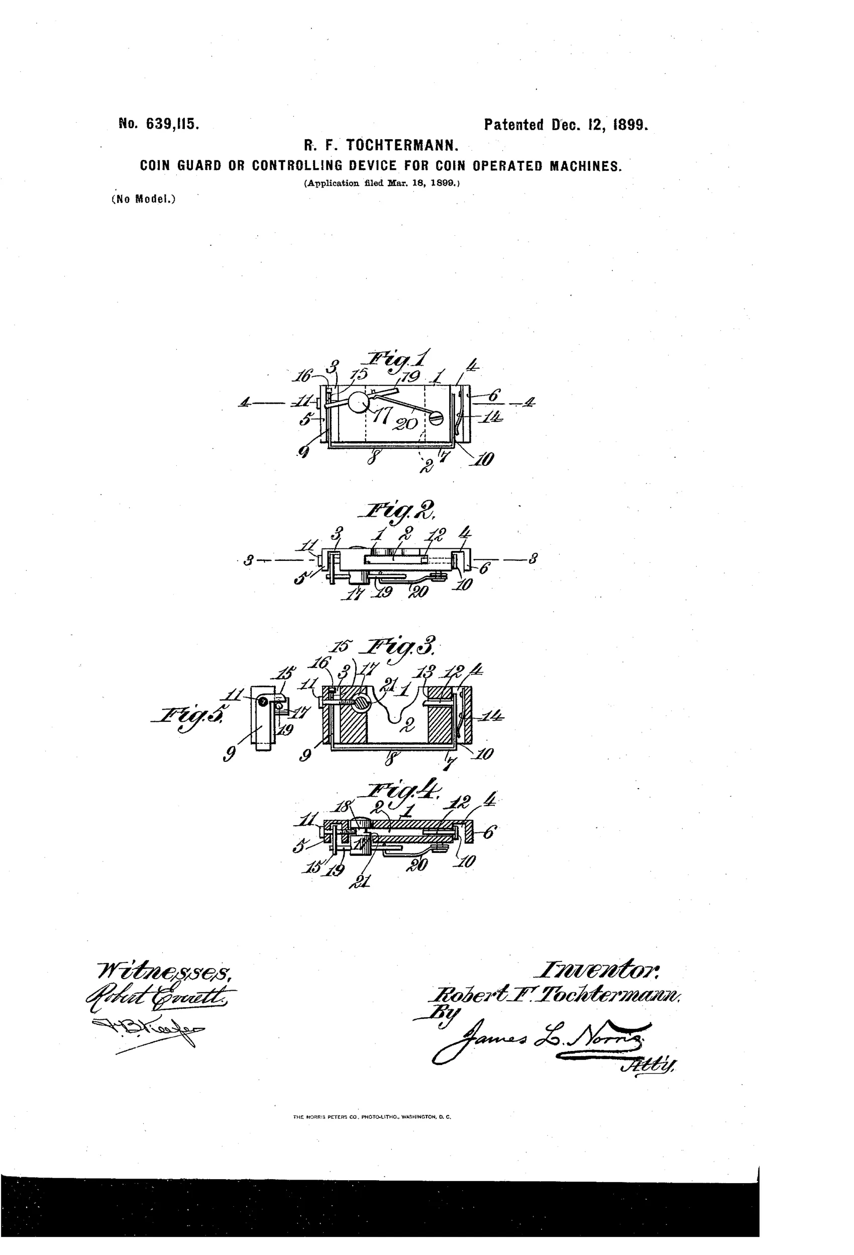
A vertical coin chute has grooved flanges holding a U-shaped gate whose upwardly-extending arms carry pins that fit loosely and can slide laterally. A leaf-spring normally holds the gate to one side, engaging a shoulder that locks the gate's bottom portion beneath the chute, blocking passage. A properly-sized coin pushed down the chute simultaneously shifts the gate arm's pin sideways (freeing it from the locking shoulder) and presses a shoulder on a separate rotating arbor, which raises a releasing lever into engagement with the gate's offset flange, swinging the gate out of the chute's path so the coin can pass through into the machine. After the coin exits, springs return the gate and arbor to their normal blocking position, while coins of the wrong size cannot actuate both the pin and the arbor shoulder simultaneously and are therefore rejected.
◉ What was claimed
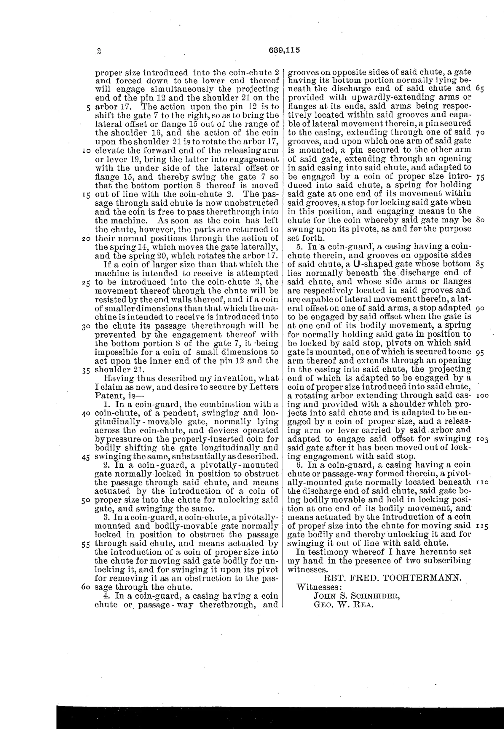
“1. In a coin-guard, the combination with a coin-chute, of a pendent, swinging and longitudinally-movable gate, normally lying across the coin-chute, and devices operated by pressure on the properly-inserted coin for bodily shifting the gate longitudinally and swinging the same, substantially as described.”
In plain English: A coin guard combining a hanging, swinging, sliding gate across the coin chute with mechanisms that a properly inserted coin pushes to both slide and swing the gate open.
◉ In the inventor’s words
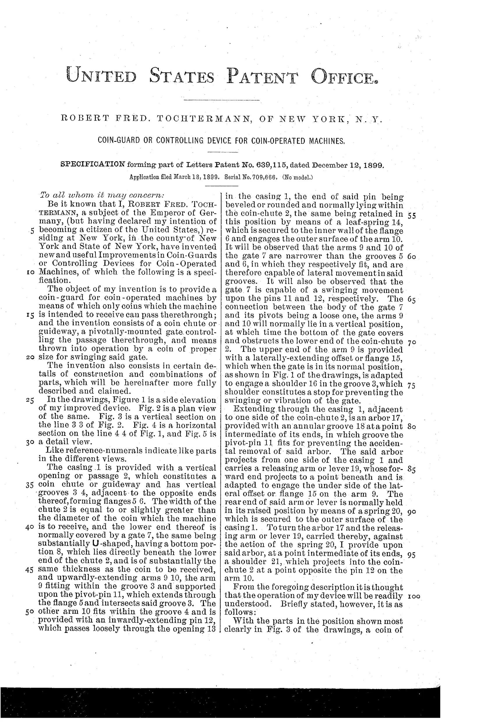
“The object of my invention is to provide a coin-guard for coin-operated machines by means of which only coins which the machine is intended to receive can pass therethrough.”— Robert Fred. Tochtermann, from the specification
Fate unknown
Like most unassigned chute-tester patents, any commercial use would have been buried anonymously inside vending machinery; a surviving mechanism traceable to this design would settle it.
◉ Patented the same day
- EJECTOR FOR COIN-DETECTORS FOR MONEY-CONTROLLED MACHINES. — Otto Jaeger and Alexander Jaeger
◉ Commentary
Most in-chute testers of the 1890s ask a coin one question at a time — are you the right diameter here, the right weight there. Tochtermann's guard is stingier: his gate stays locked unless the coin does two things simultaneously. It has to shift the gate's pin sideways to clear a locking shoulder, and at the same instant press a shoulder on a rotating arbor that lifts a releasing lever into the gate's offset flange. Only a coin of exactly the right size can reach both trigger points at once. A slug that's too small frees one latch but not the other; too large and it jams before either moves. That's a coincidence lock, essentially — the same logic a good padlock uses.
The drawing rewards a slow look. Figures 1 and 3 show how much machinery is packed into a box barely bigger than the coin itself: the U-shaped gate with its loose-riding pins in grooved flanges, the leaf spring biasing everything to the blocking position, the arbor detail pulled out in Fig. 5. Everything resets by spring after the coin drops through, so it needs no attendant and no escapement timing.
It sits squarely in the great 1890s scramble to make coin-op machines slug-proof — a refinement, not a first, and one of dozens filed that decade. But the two-conditions-at-once locking logic is genuinely sharper than the average weighted flap, even if all those pins and shoulders would have made it fussy to manufacture and prone to gumming with pocket lint.
Commentary by Claude, The Counterfeit Coin Detector Patent Archive’s resident enthusiast