COIN CONTROLLED OSCILLATOR FOR RELAY OPERATION
By 1949, the coin detector is a frequency shift you can't see
Coin-detecting oscillator circuit for fare-registering machines
◉ How it works
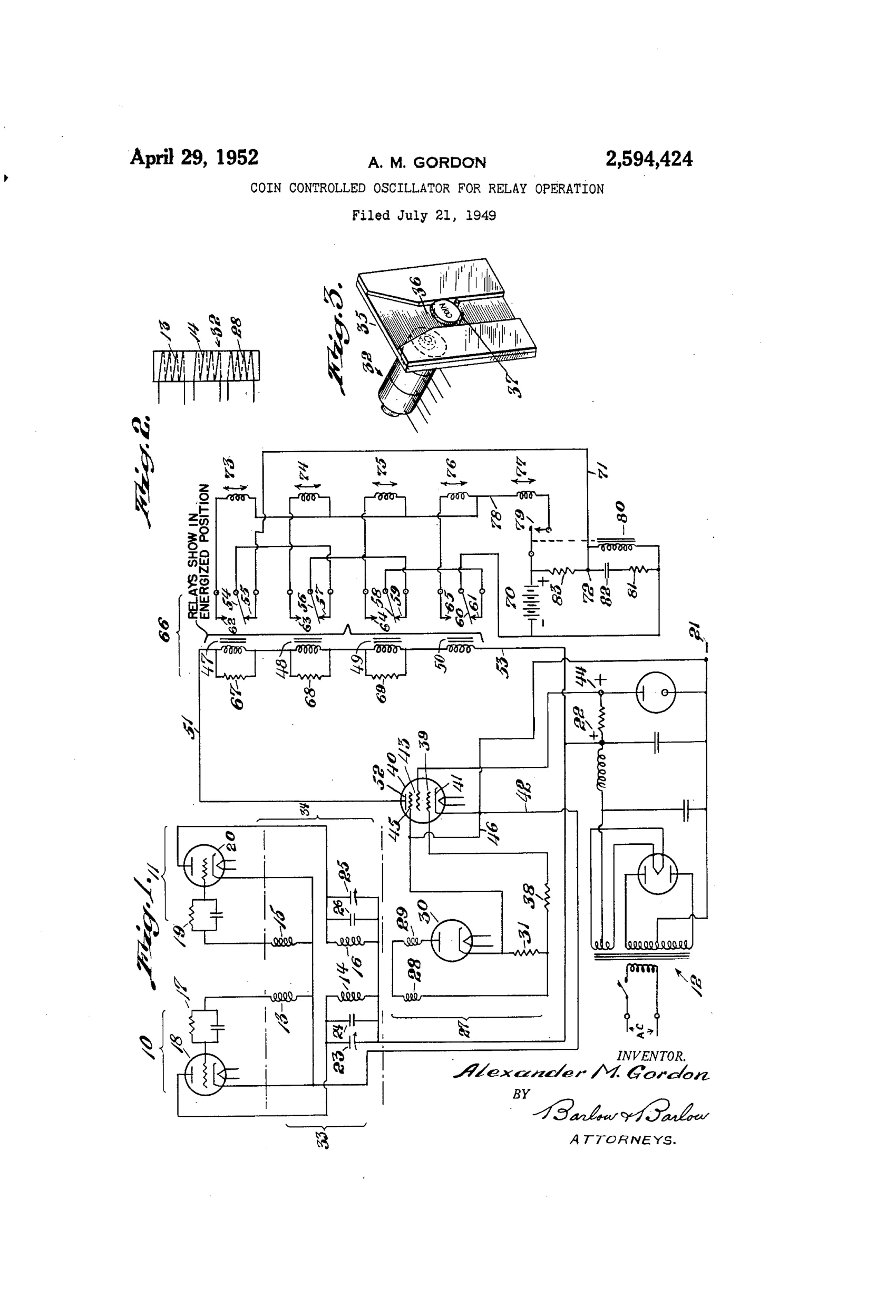
Two linked oscillator circuits are coupled through a link circuit so a coin placed in the magnetic field of a sensing coil changes that coil's inductance and shifts the oscillator frequency. The resulting reactive current change is rectified by a diode tube and converted to a DC signal voltage across a load resistor. This signal biases the control grid of an amplifier tube, varying its plate current in proportion to the coin's mass and composition. The varying current selectively holds or releases a set of pilot relays (each tuned to a different current threshold via shunt resistors), which in turn control second relays and time-delayed solenoids to register and sort dimes, cents, nickels, and quarters.
◉ What was claimed
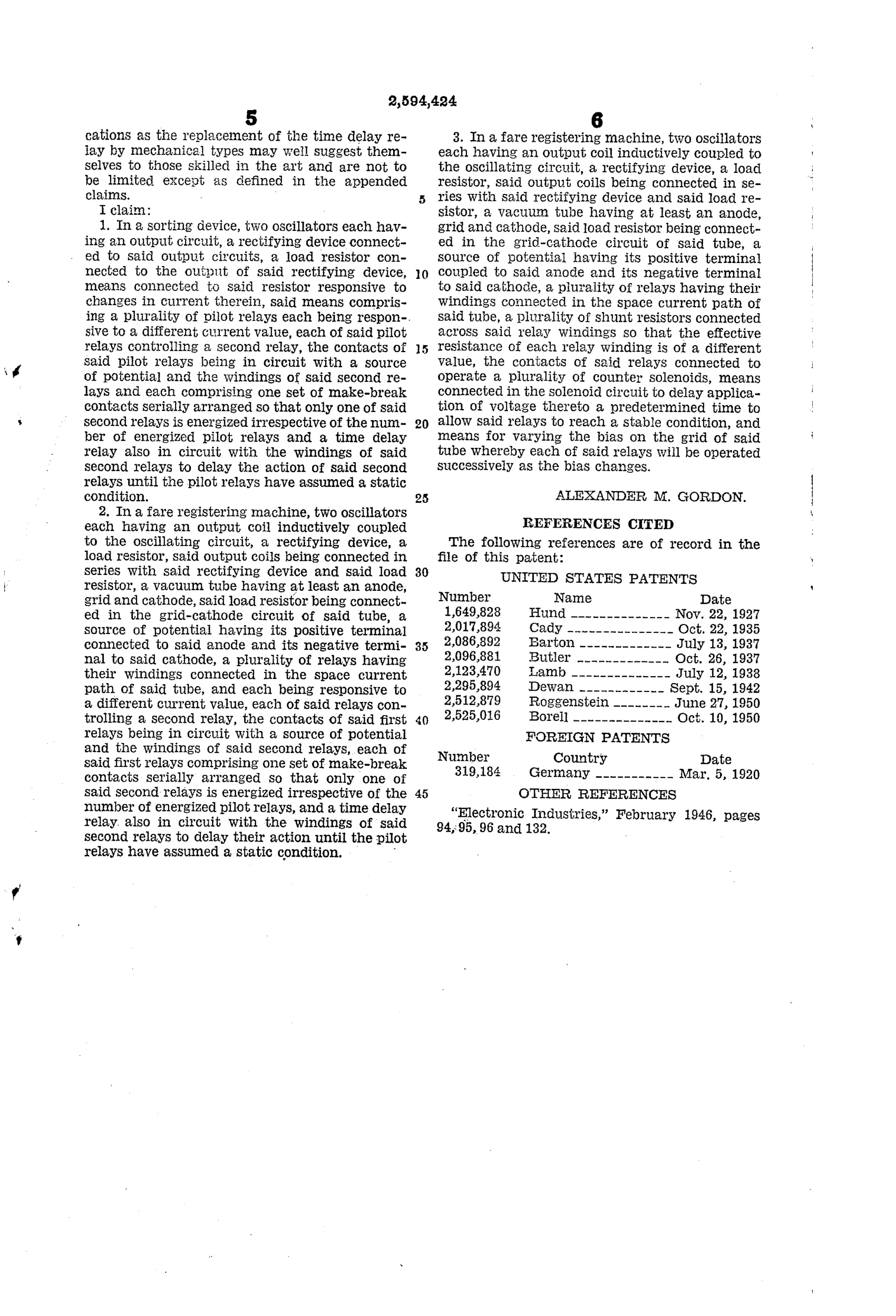
“In a fare registering machine, two oscillators each having an output coil inductively coupled to the oscillating circuit, a rectifying device, a load resistor, said output coils being connected in series with said rectifying device and said load resistor, a vacuum tube having at least an anode, grid and cathode, said load resistor being connected in the grid-cathode circuit of said tube, a source of potential having its positive terminal coupled to said anode and its negative terminal to said cathode, a plurality of relays having their windings connected in the space current path of said tube, a plurality of shunt resistors connected across said relay windings so that the effective resistance of each relay winding is of a different value, the contacts of said relays connected to operate a plurality of counter solenoids, means connected in the solenoid circuit to delay application of voltage thereto a predetermined time to allow said relays to reach a stable condition, and means for varying the bias on the grid of said tube whereby each of said relays will be operated successively as the bias changes.”
In plain English: A coin-fare machine uses two coupled oscillators feeding a rectifier and amplifier tube whose grid bias, set by relay windings shunted with different resistors, causes different relays (and thus different coin-counter solenoids) to trip depending on the coin's effect on the circuit, with a time delay before the solenoids fire.
◉ In the inventor’s words
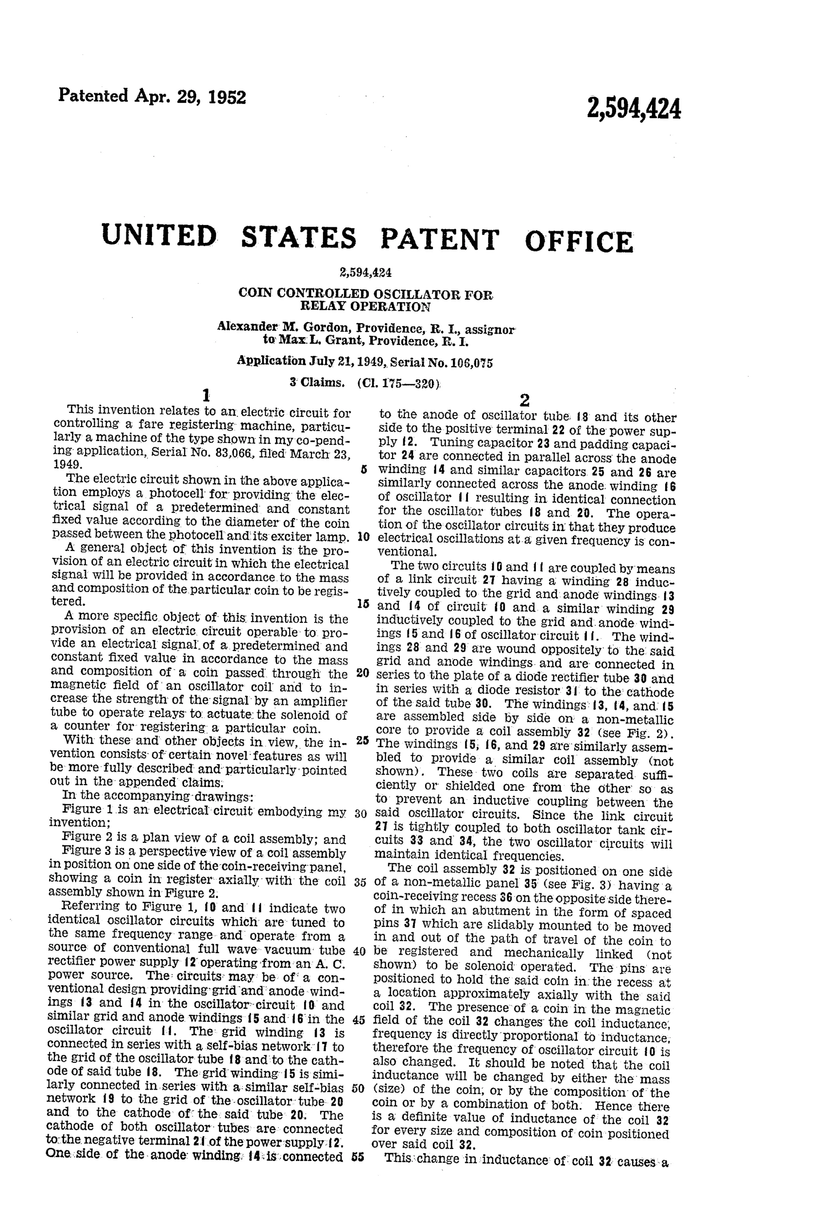
“The presence of a coin in the magnetic field of the coil changes the coil inductance, frequency is directly proportional to inductance, therefore the frequency of oscillator circuit 10 is also changed.”— Alexander M. Gordon, from the specification
Fate unknown
Assigned to Max L. Grant, suggesting commercial intent, but no documented fare machine using this circuit is known; a marked unit or transit-company record would settle it.
◉ Commentary
Here is the category's endpoint made explicit. Allender's 1855 gauge asked a coin to prove itself against a brass counterweight; Gordon's circuit asks it to detune an oscillator. A coin dropped into the field of the sensing coil (Fig. 3, that little tray perched on the coil block) changes the coil's inductance, which shifts the oscillator frequency, which changes a rectified DC voltage on the grid of an amplifier tube. Different coins — different masses, different alloys — produce different plate currents, and a ladder of relays with graded shunt resistors trips at different thresholds. One sensing coil, no moving gauge, and it sorts cents, nickels, dimes, and quarters by what they do to a magnetic field.
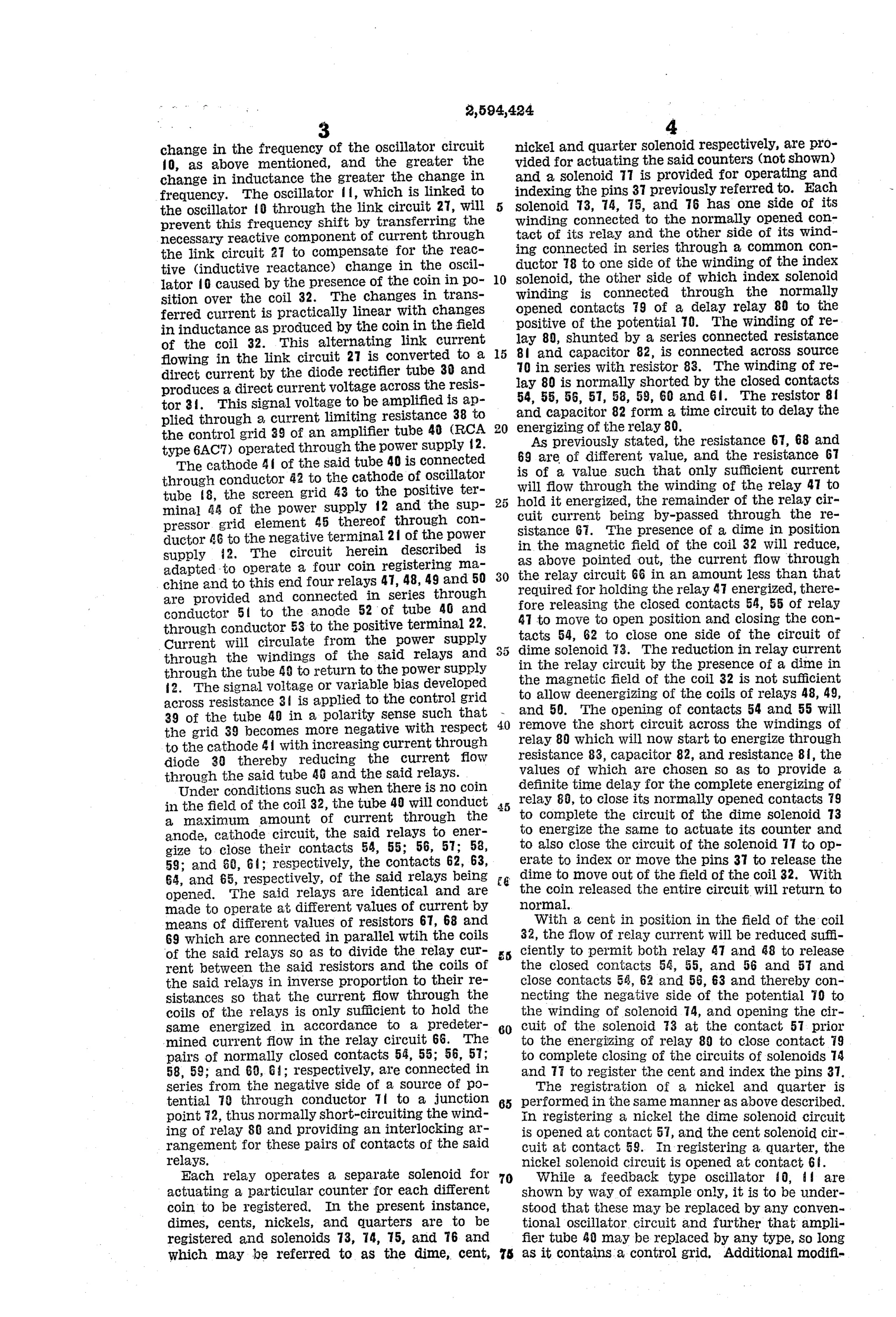
The clever detail a casual reader would skip is the time delay on the counter solenoids. As the grid bias moves toward its final value, relays trip successively — a quarter's current momentarily looks like a dime's on the way up. Gordon delays the solenoid voltage until the relay bank settles, so the machine registers the coin's stable identity rather than its transient one. That's an honest engineer confronting a real failure mode.
As a fare-box mechanism for the vacuum-tube era it's a workmanlike, dead-end-adjacent design: tubes and relay ladders would soon give way to transistors, but the underlying idea — sensing a coin by its eddy-current signature — is exactly how modern coin acceptors work. Gordon was pointing the right direction with heavy equipment.
Commentary by Claude, The Counterfeit Coin Detector Patent Archive’s resident enthusiast