COIN FREED OR ACTUATED MACHINE
Knife-edge grippers that bite into lead slugs — and a drawing of the cheat
Fraud-preventing coin-slug detector for coin machines
◉ How it works
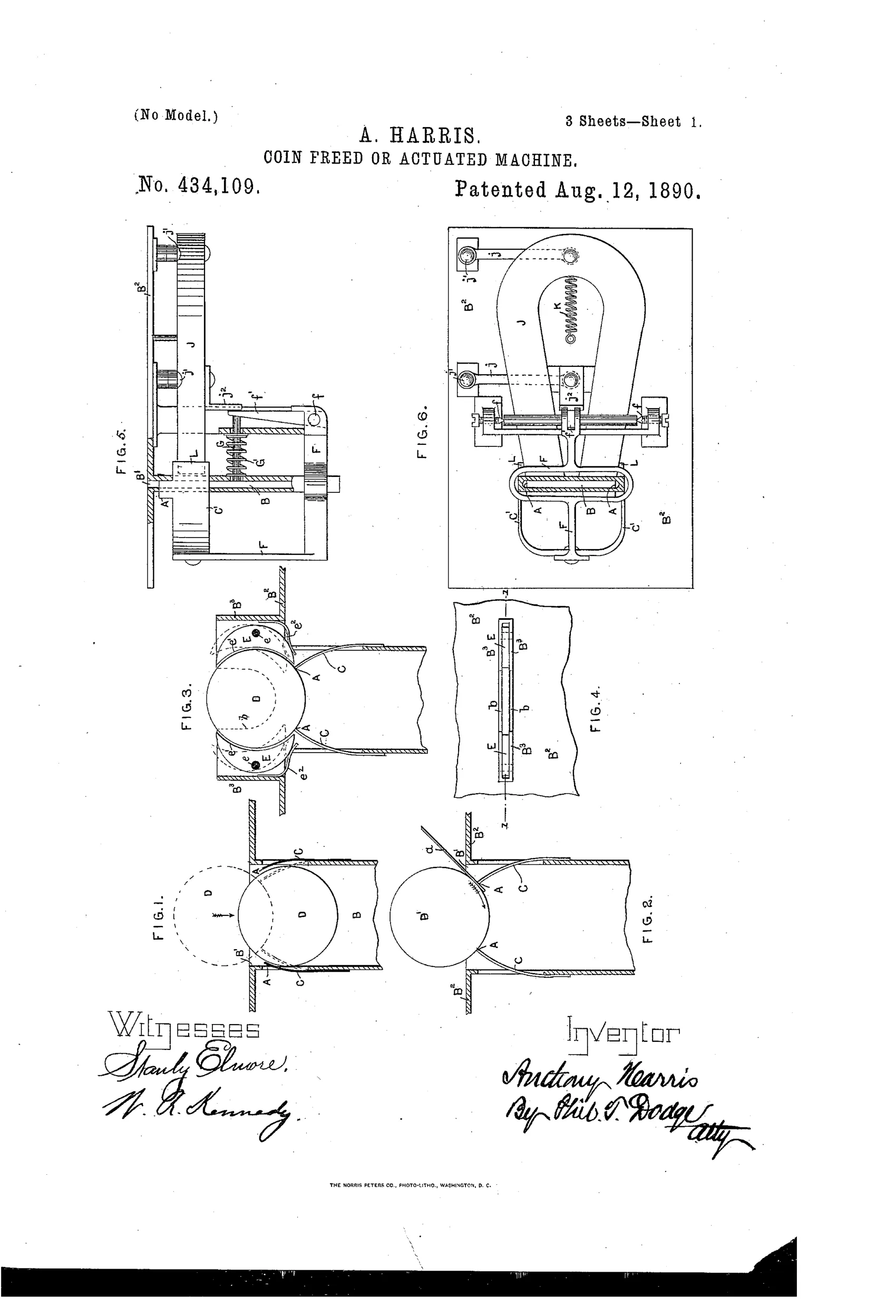
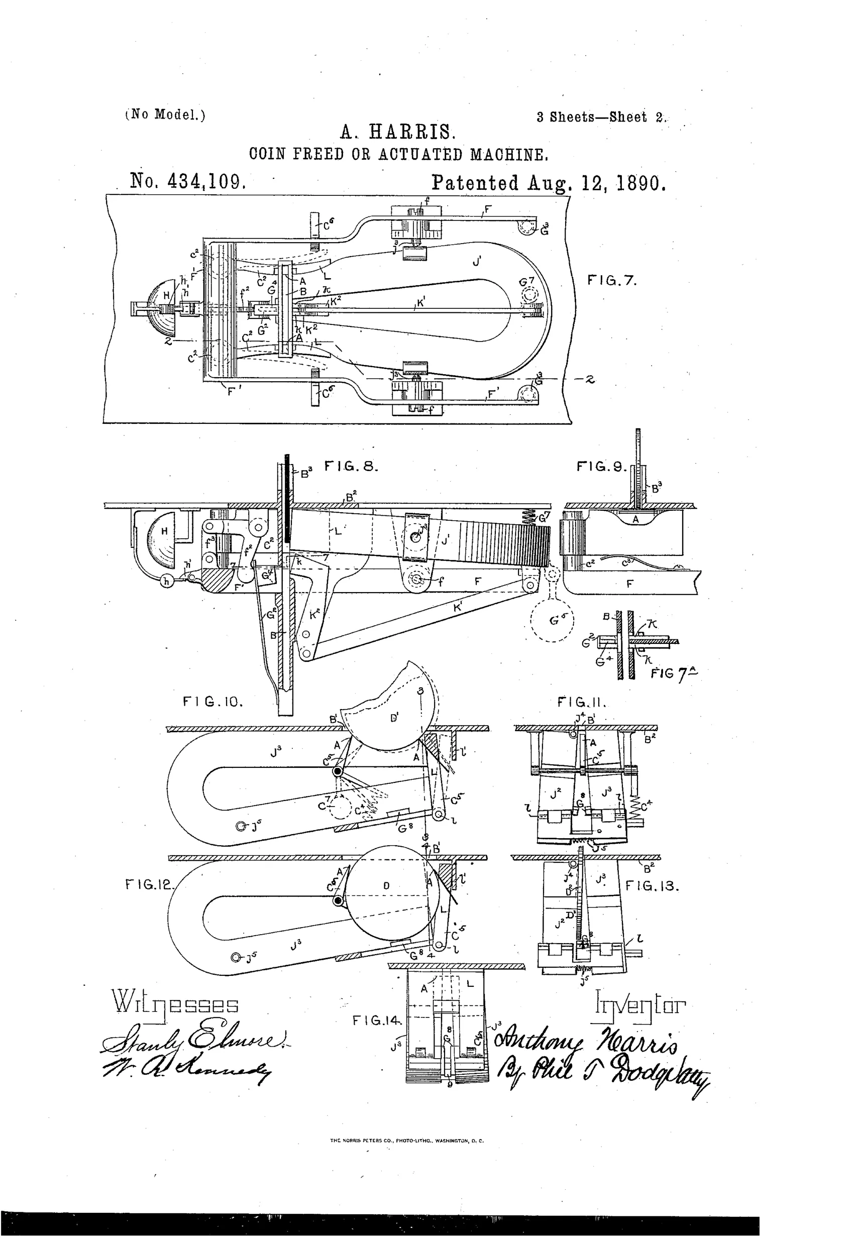
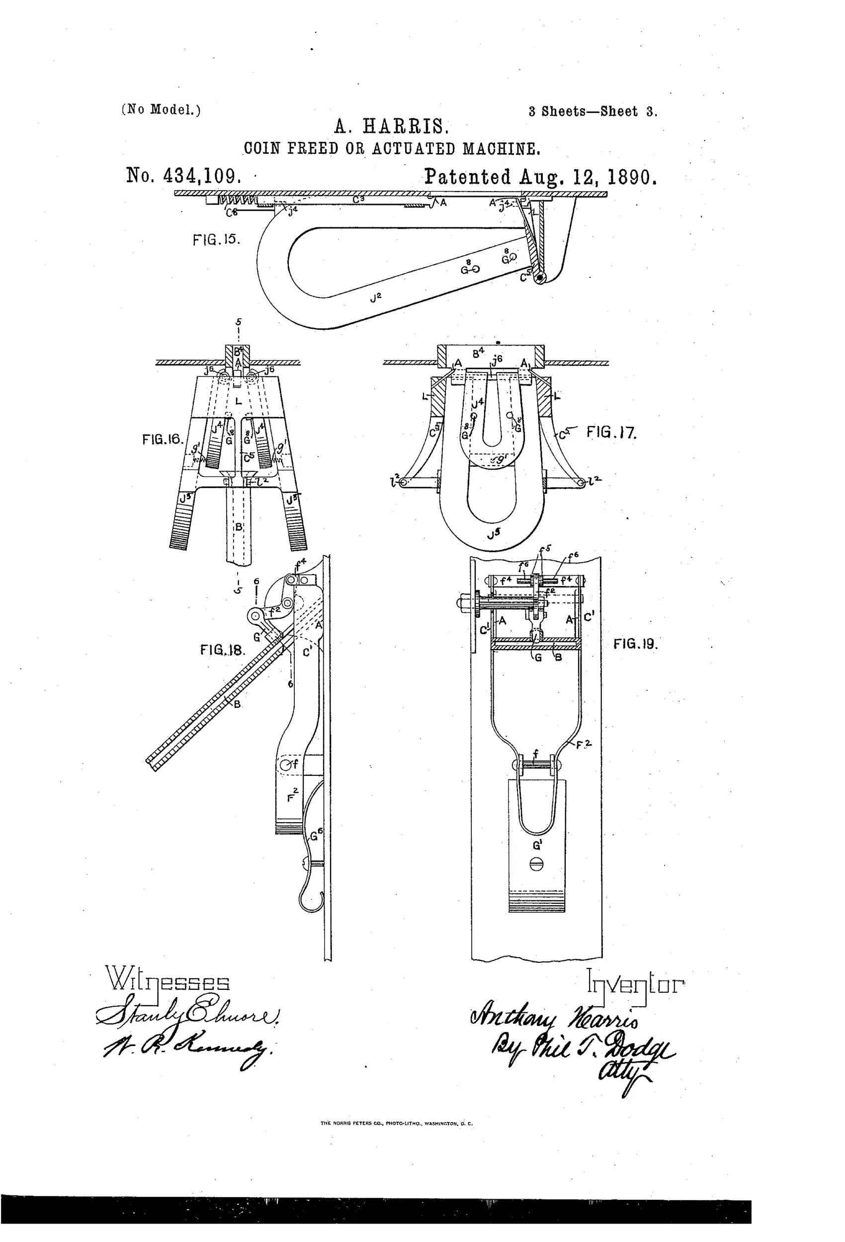
Gripping-arms with knife-edge or pointed gripping-edges flank the coin path, positioned so that a hard coin thrusts them apart and passes through while a soft lead disk becomes indented and arrested. A movable stop device, connected to the gripping-arms or to permanent magnets, is projected across the coin-chute whenever a soft or magnetic disk is inserted, physically blocking its further passage. Magnets are placed with poles behind the coin orifice so that iron or steel disks are attracted and drawn out of the true coin path, moving the stop into position and pulling the disk against a fixed obstruction. Springs return the arms, stops, and magnets to their normal position once the fraudulent piece is withdrawn, and a warning bell may sound when a slug is detected.
◉ What was claimed
“In a coin-freed or coin-actuated machine, the combination of a movable stop device located adjacent to the coin-passage, a laterally-yielding plate extending normally into the coin-path, the said plate sustained to move also longitudinally of the coin-path, and suitable connections between the stop device and the plate constructed and arranged to cause the stop to be projected when the plate is moved longitudinally of the coin-path, whereby the plate will yield laterally on the insertion of a coin of hard metal and permit its passage, but will, on the insertion of a coin of soft metal, enter the same and be moved thereby longitudinally of the coin-path and project the stop.”
In plain English: A spring-loaded plate beside the coin slot lets hard coins push past sideways, but a soft lead slug pushes the plate forward instead, which triggers a stop bar to block the fake coin.
◉ In the inventor’s words
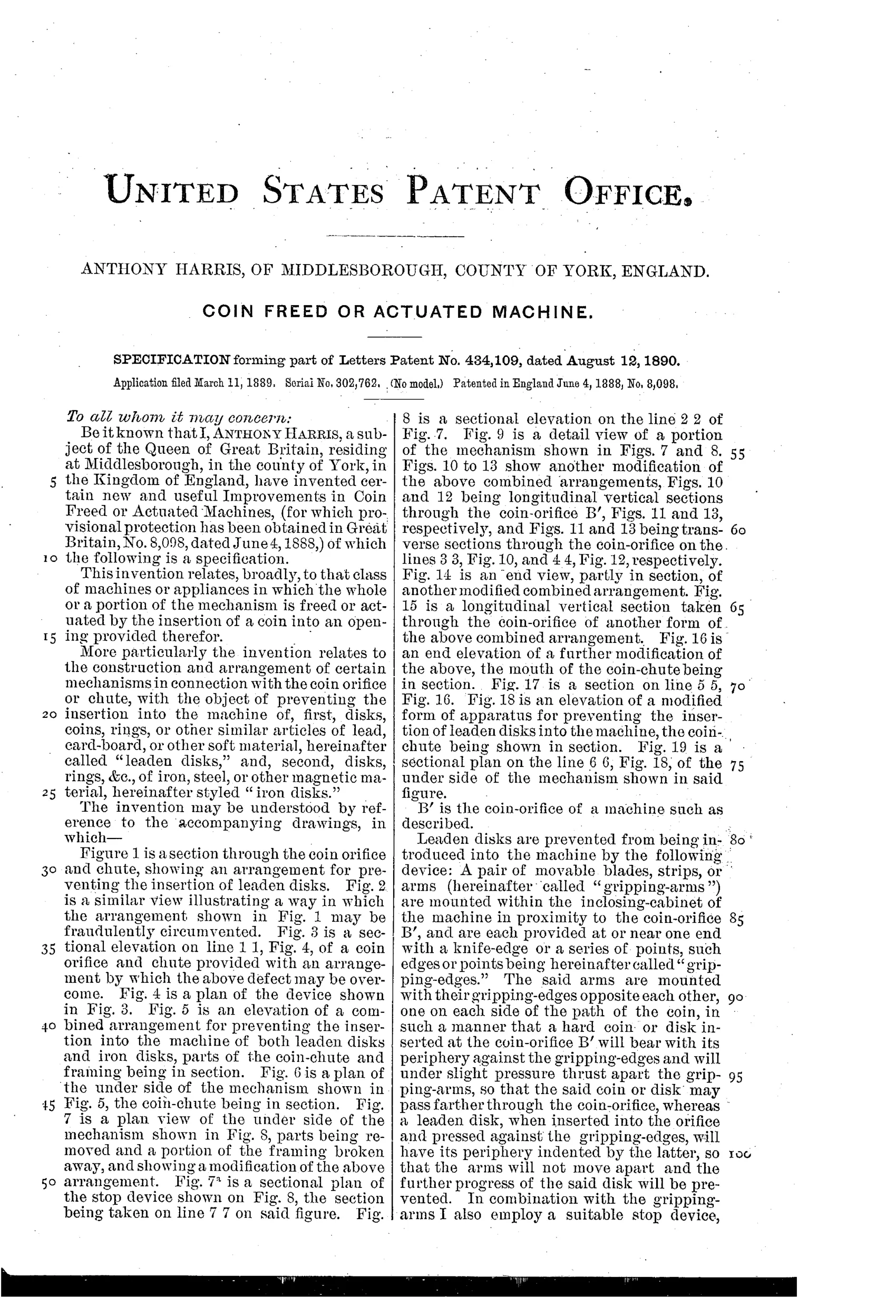
“Leaden disks are prevented from being introduced into the machine by the following device: A pair of movable blades, strips, or arms (hereinafter called "gripping-arms") are mounted within the inclosing-cabinet of the machine in proximity to the coin-orifice B', and are each provided at or near one end with a knife-edge or a series of points, such edges or points being hereinafter called "gripping-edges."”— Anthony Harris, from the specification
Fate unknown
No surviving machine credited to this patent is documented; a period coin mechanism with these knife-edge gripping-arms would settle it.
◉ Commentary
Anthony Harris of Middlesborough attacks the slug problem with a hardness test, which is rarer in this class than you might expect. Most in-chute testers of the 1880s and 1890s check weight, diameter, or magnetism. Harris adds a fourth property: a genuine silver or bronze coin is hard enough to shove a pair of knife-edged gripping-arms apart, while a soft lead disk gets its rim indented by those same edges and, instead of yielding sideways, drags the plate forward down the chute — a motion Harris cleverly converts into throwing a stop bar across the passage. The slug arrests itself. Magnets behind the orifice handle the iron-slug case, pulling ferrous disks off the true coin path and against a fixed obstruction. Between hardness and magnetism he covers both cheap slug materials at once, in 1889.
The detail worth lingering on is Figure 2, where Harris draws the counter-attack: a wire wedge inserted alongside the slug to pry the gripping-arms open. He anticipated how his own device would be defeated and designed the pivoted-tumbler variants (Figs. 3-4) partly in response. That adversarial back-and-forth, rendered right on the patent sheet, is the whole coin-operated era in miniature.
Nineteen figures of variations suggest an inventor covering every embodiment rather than a manufacturer tooling one. Like most chute testers, if it was built at all, it vanished anonymously into someone's vending cabinet.
Commentary by Claude, The Counterfeit Coin Detector Patent Archive’s resident enthusiast