The Counterfeit Coin Detector Patent Archive

Every device ever patented to catch a bad coin

Magnet test

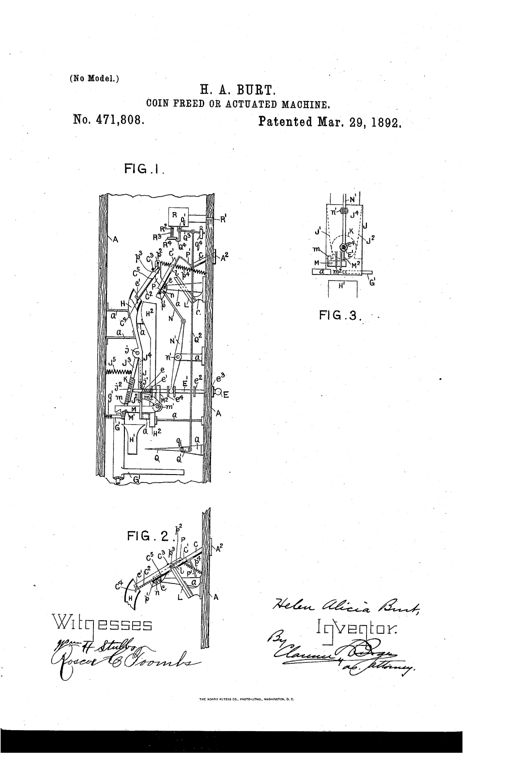
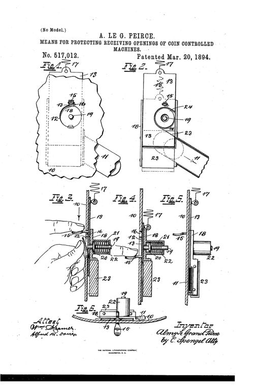
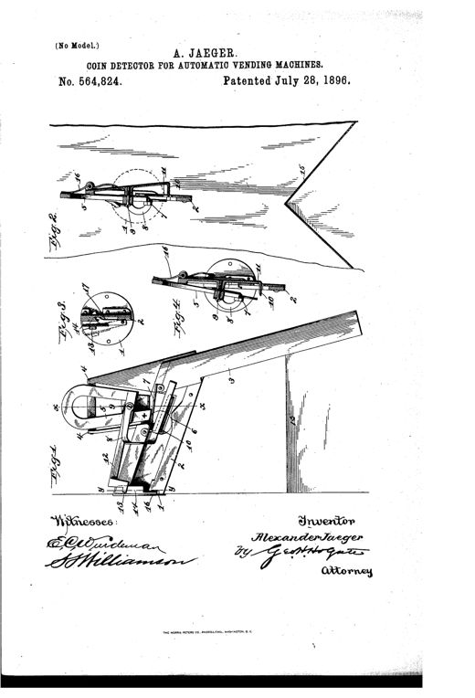
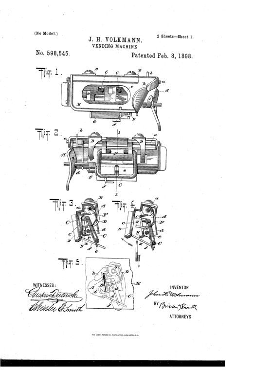
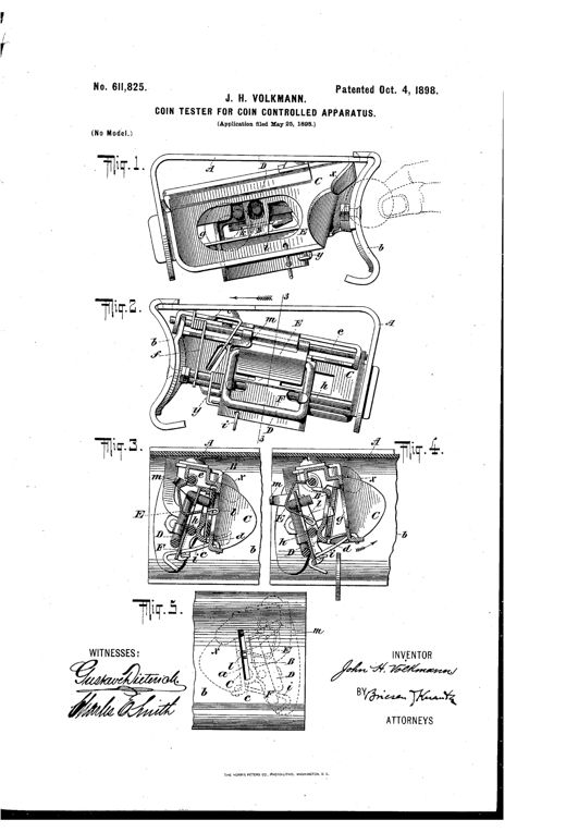
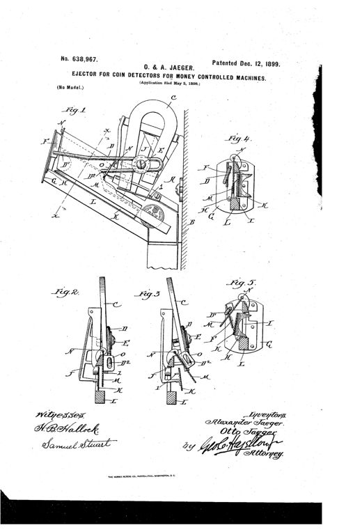
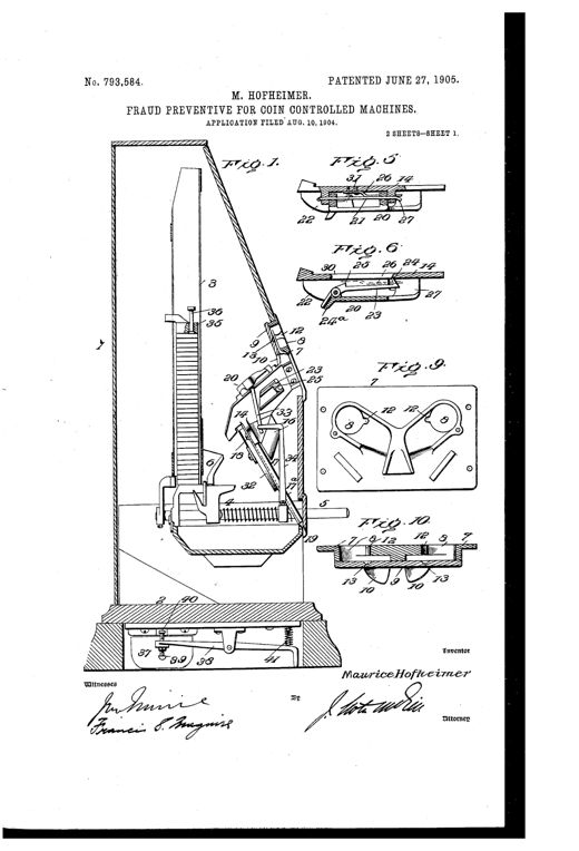
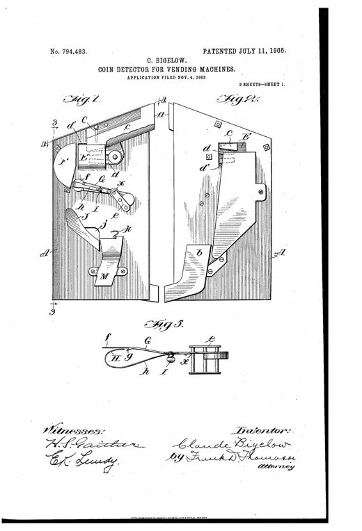
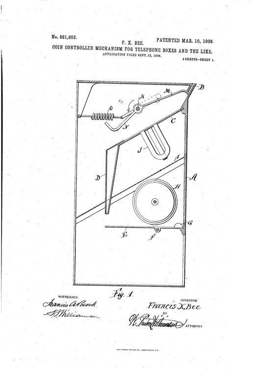
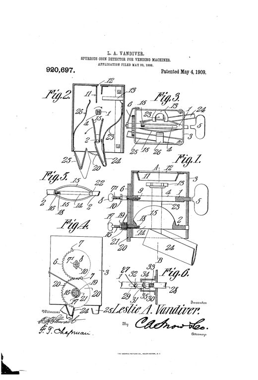
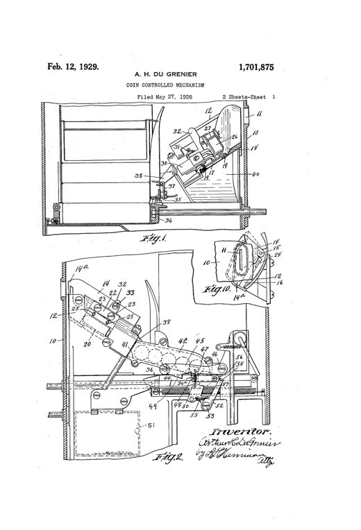
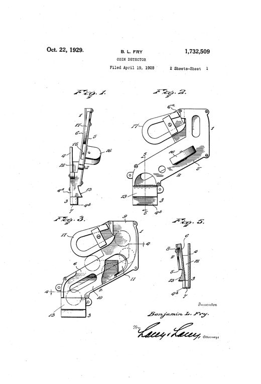
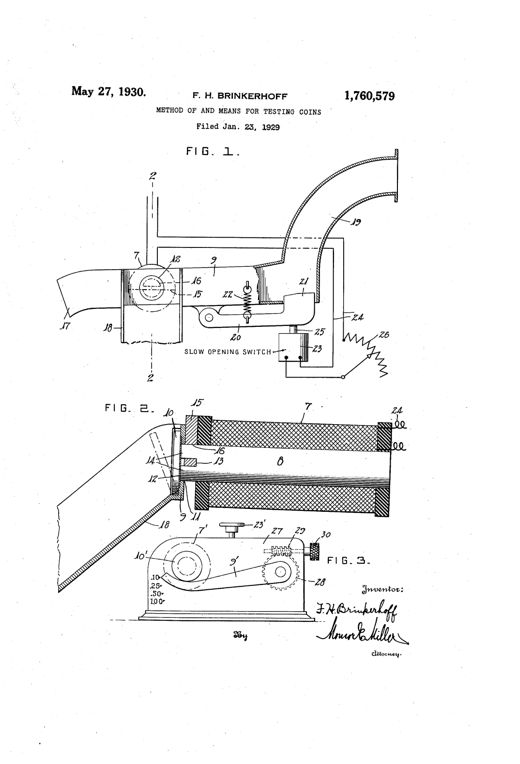
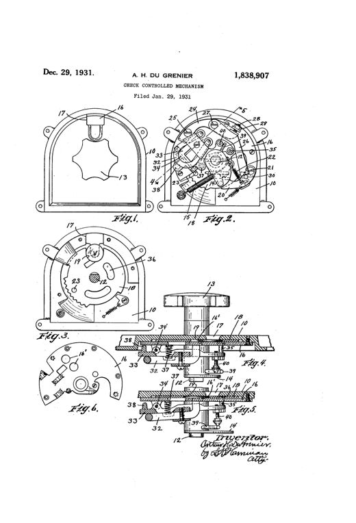
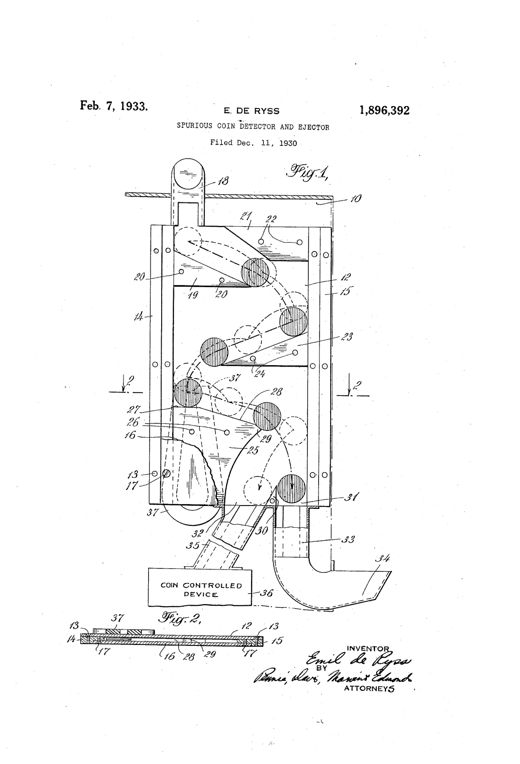
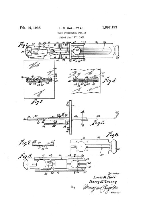
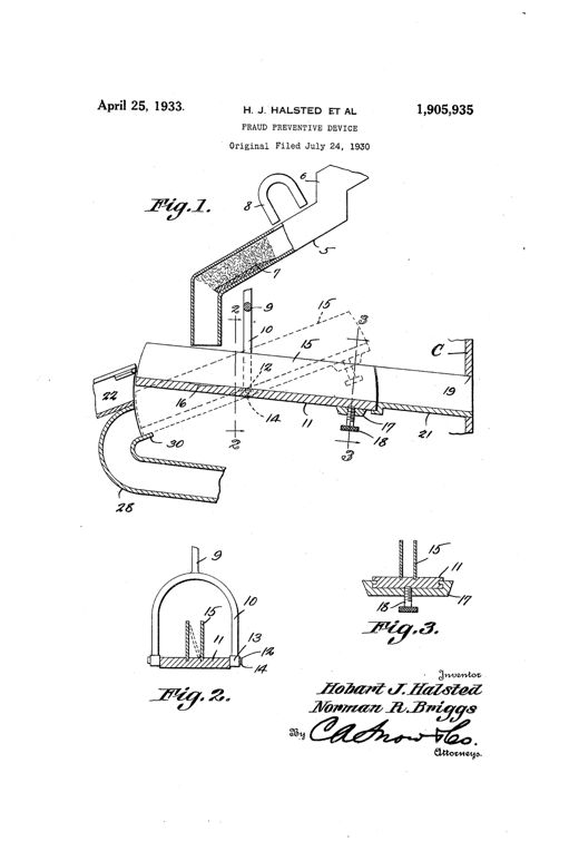
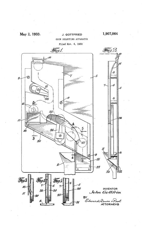
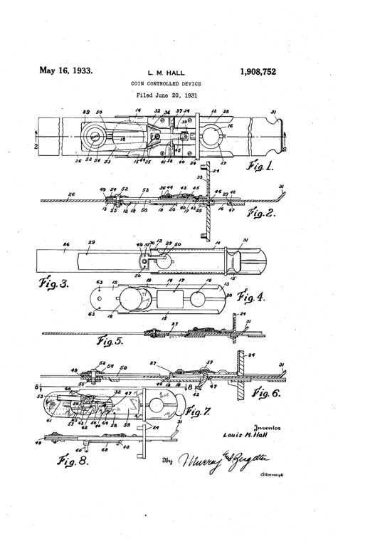
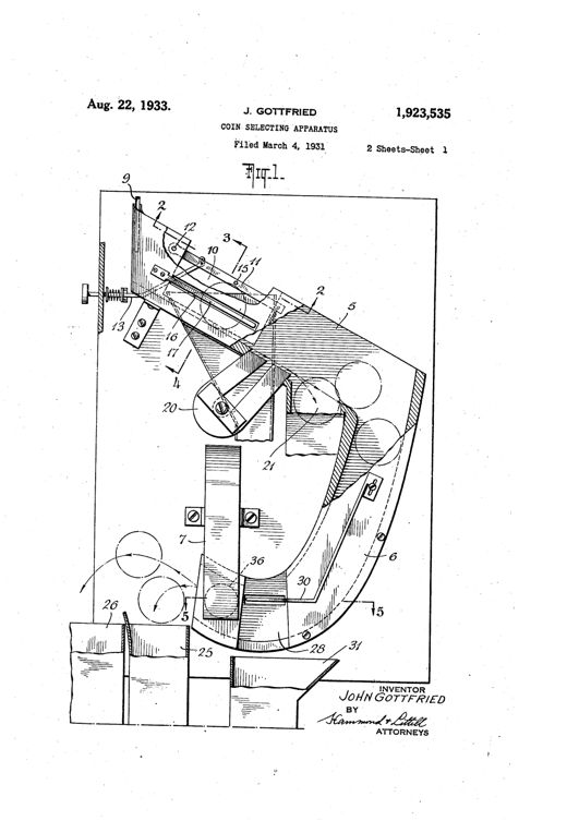
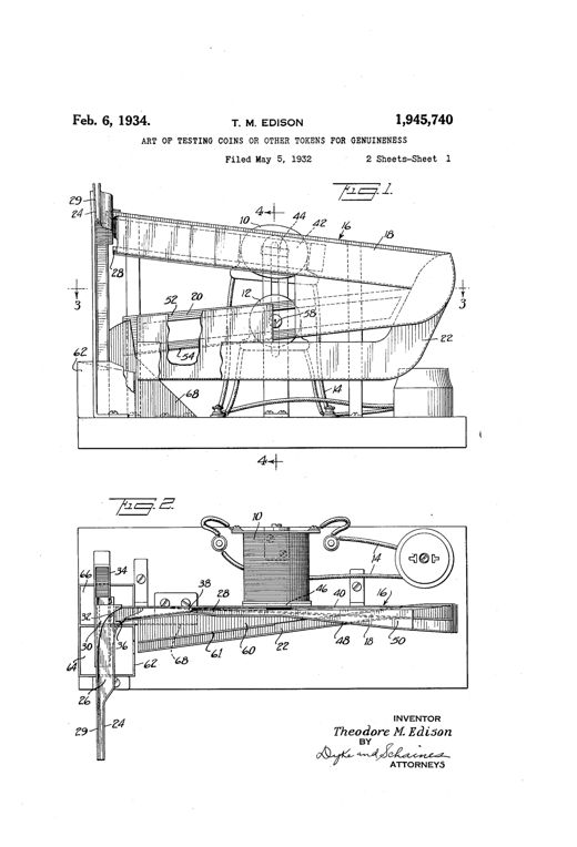
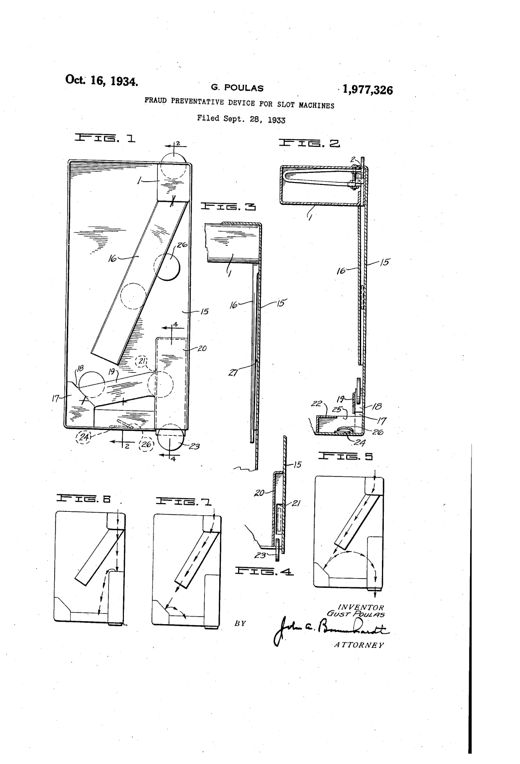
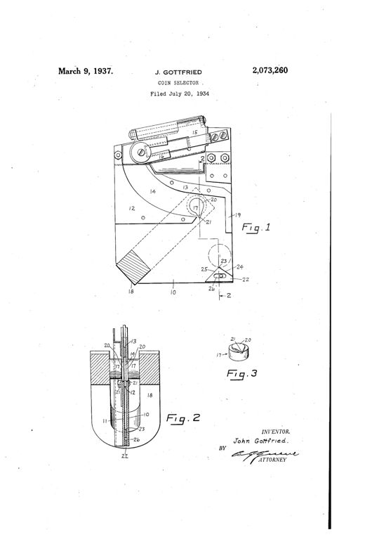
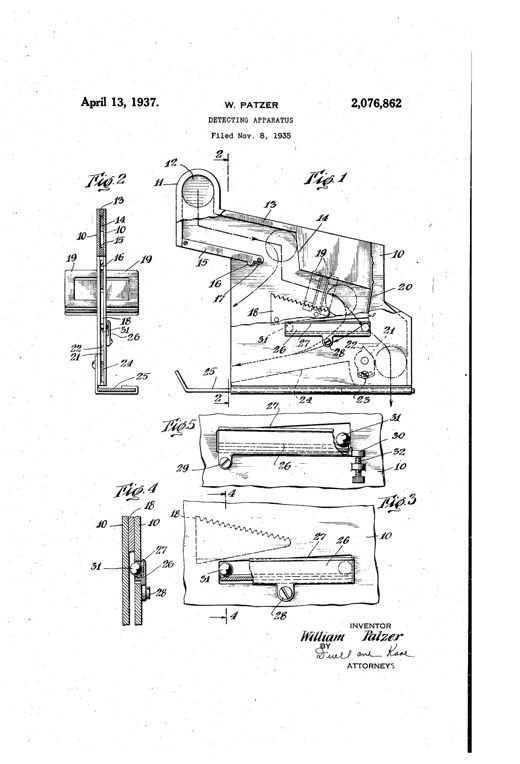
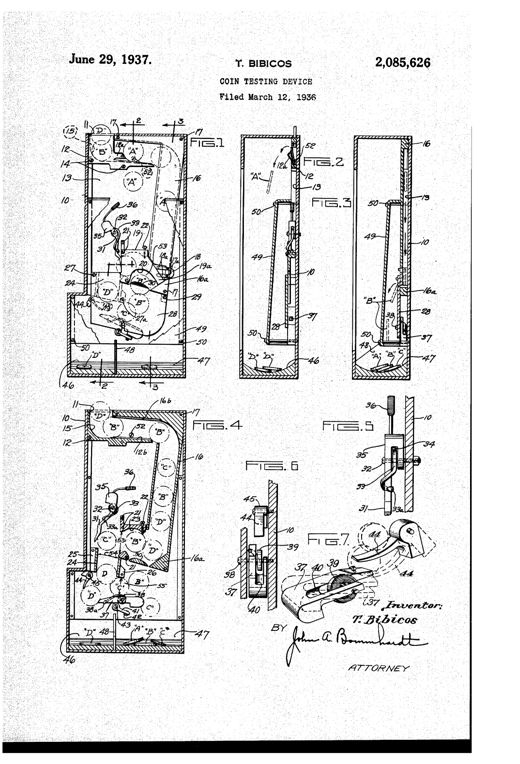
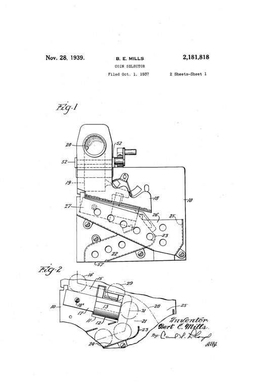
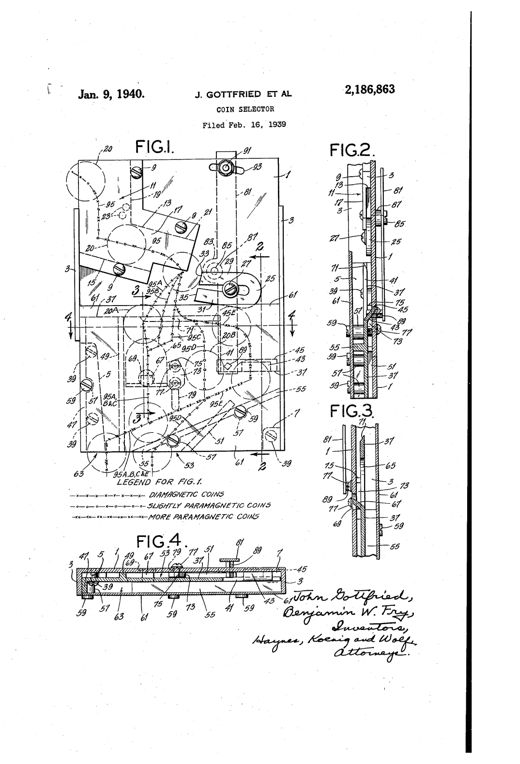
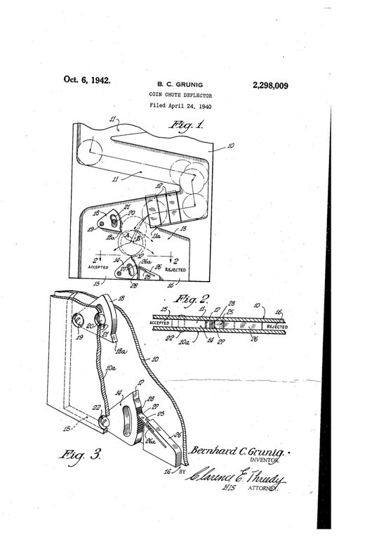
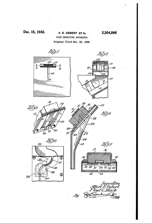
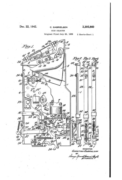
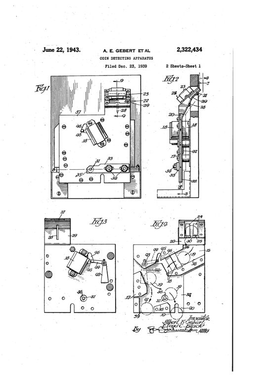
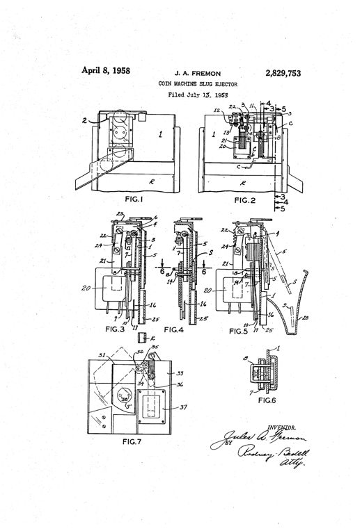
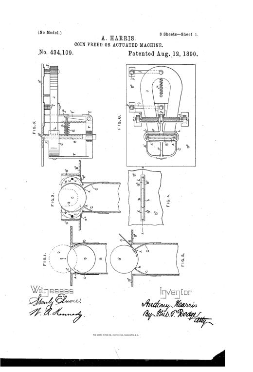
Patent drawing sheets showing multiple mechanical diagrams of a coin-chute with pivoted gripping-arms, magnets, springs, and sliding stops designed to detect and block counterfeit lead or iron coin slugs.COIN FREED OR ACTUATED MACHINEAnthony Harris · August 12, 1890Patent line drawing showing a tall coin-operated cabinet mechanism (Fig. 1) with a hinged coin slide, magnet, push-handle, camera and dash-pan assembly, alongside a detail front view of the money-box (Fig. 3) and a partial side view (Fig. 2) of the slide linkage.COIN FREED OR ACTUATED MACHINE.Helen Alicia Burt · March 29, 1892Patent drawing showing six figures of a coin-slot protection mechanism with a reciprocating slide, spring-loaded ejector, magnet, and coin chute, plus hand-operated views of a coin being inserted.MEANS FOR PROTECTING RECEIVING-OPENINGS OF COIN-CONTROLLED MACHINES.Almy Le Grand Peirce · March 20, 1894Patent drawing of a 19th-century coin detector showing an angled chute with a pivoted magnet, lever, and push-off mechanism for trapping and ejecting false iron or steel coins from a vending machine.COIN-DETECTOR FOR AUTOMATIC VENDING-MACHINES.Alexander Jaeger · July 28, 1896Patent drawing of a mechanical coin-tester showing a hinged plate assembly with a pivoted magnet, coin track, and washer-catcher arm mounted inside a tall vending-machine cabinet.VENDING-MACHINEJohn H. Volkmann · February 8, 1898Patent drawing of a coin-tester mechanism showing an inclined housing with a slotted plate, pivoted magnet, and hooked washer-catcher arm inside a metal frame, illustrated from multiple side and sectional views.COIN-TESTER FOR COIN-CONTROLLED APPARATUS.John H. Volkmann · October 4, 1898Patent drawing showing a coin-detector ejector mechanism with a pivoted horseshoe magnet, bent rod, incline bar, and push-off plate mounted on a bracket, with five labeled cross-sectional figures illustrating the mechanism in normal and coin-actuated positions.EJECTOR FOR COIN-DETECTORS FOR MONEY-CONTROLLED MACHINES.Otto Jaeger and Alexander Jaeger · December 12, 1899Patent line drawing of a tall vending machine cabinet with an internal coin guideway mechanism, pivoted castings with hooked fingers, chutes, and an ejector rod, shown in section and detail views.FRAUD-PREVENTIVE FOR COIN-CONTROLLED MACHINESMaurice Hofheimer · June 27, 1905Patent drawing of a mechanical coin detector showing an inclined chute with a magnet and pivoted retarding arm feeding into a curved segmental chute, which delivers coins onto a spring-loaded pivoting tilting bar mounted inside a vending machine case.COIN-DETECTOR FOR VENDING-MACHINES.Claude Bigelow · July 11, 1905Patent drawing of a telephone coin box mechanism showing coin slots, chutes with magnets, a crank-operated shaft with kick-off fingers, and a weighted lever striking a bell to signal valid coin deposit.COIN-CONTROLLED MECHANISM FOR TELEPHONE-BOXES AND THE LIKE.Francis X. Bee · March 10, 1908Patent drawing of a rectangular vending-machine coin box housing two parallel slotted shafts with gear wheels, springs, set screws, and diverging chutes, shown in six views labeled Fig. 1 through Fig. 6.SPURIOUS-COIN DETECTOR FOR VENDING-MACHINES.Leslie A. Vandiver · May 4, 1909Patent drawing sheets showing exploded mechanical views of a coin-controlled dispensing machine with an inclined disk passage, gauge plates, pivoted deflecting arms, a magnet, and a reciprocating coin carrier tray, labeled with numbered reference lines.COIN-CONTROLLED MECHANISMArthur H. Du Grenier · February 12, 1929Exploded and assembled mechanical drawings of a metal coin chute assembly showing separate side walls, an intermediate wall with an opening, a horseshoe magnet, and a toothed rotating detector wheel that sorts coins from slugs into two discharge paths.COIN DETECTORBenjamin L. Fry · October 22, 1929Patent drawing showing a coin-testing chute with an electromagnet coil, lever-operated slow-opening switch, and circuit diagram, plus a second bench-top device with an adjustable coin-support arm and graduated scale for dimes through dollars.METHOD OF AND MEANS FOR TESTING COINSFrederic H. Brinkerhoff · May 27, 1930Patent drawing sheet showing an arch-shaped coin-mechanism casing with a star-shaped coin slot handle, an internal disk-like coin carrier with locking levers and a pivoted horseshoe magnet, and cross-sectional side views labeling numbered parts such as the shaft, magnet support, spring, and locking pin.CHECK CONTROLLED MECHANISMArthur H. Du Grenier · December 29, 1931Mechanical drawing of a coin detector housing showing a zigzag arrangement of inclined metal anvils, vertical guide strips, an overhead deflecting anvil, a magnet, and two discharge chutes leading to a coin-controlled device and a return cup, with a side cross-section below labeled Fig. 2.SPURIOUS COIN DETECTOR AND EJECTOREmil de Ryss · February 7, 1933Patent drawing showing a coin slot mechanism with a support plate, sliding coin-carrying strip with handle, housing with lateral flanges, ridges and studs for anti-fraud protection, and a magnet-equipped trigger arm, illustrated in seven labeled figures including top, side, and cross-sectional views.COIN CONTROLLED DEVICELouis M. Hall · February 14, 1933Patent drawing showing an inclined coin guide tube feeding into a tiltable weighing scale with adjustable counterweight, guide strips, and separate receiving and return channels, with two smaller cross-section figures below detailing the hanger yoke and weight assembly.FRAUD PREVENTIVE DEVICEHobart J. Halsted · April 25, 1933Patent drawing showing a vertical coin chute mechanism with labeled magnets, pivots, and diverging passages, plus side-view and cross-sectional details of the coin runway construction.COIN SELECTING APPARATUSJohn Gottfried · May 2, 1933Patent drawing showing a long sliding guide plate and strip mechanism with coin apertures, spring trigger, magnet, and abutment arm, illustrated in eight cross-sectional and plan views labeled Fig. 1 through Fig. 8.COIN CONTROLLED DEVICELouis M. Hall · May 16, 1933Patent drawing of a coin-selecting apparatus showing an inclined upper chute with a movable top rail and ejecting spring leading into a vertical J-shaped chute flanked by magnet pole pieces, with numbered parts and a lower coin return tray.COIN SELECTING APPARATUSJohn Gottfried · August 22, 1933Patent drawing of an inclined chute apparatus with two electromagnets positioned along the coin path, showing a coin rolling on edge past the magnets and being deflected into separate collection compartments based on its metal composition.ART OF TESTING COINS OR OTHER TOKENS FOR GENUINENESSTheodore M. Edison · February 6, 1934Patent drawing of a rectangular slot-machine coin box showing an inclined coin slide leading to a metallic bouncing block, with side sections illustrating the paths taken by genuine coins versus thin or soft metal slugs into a slug pocket.FRAUD PREVENTATIVE DEVICE FOR SLOT MACHINESGust Poulas · October 16, 1934Patent drawing of a coin selector mechanism showing a side elevation with coin chute, magnet pole pieces with pointed projections, and a pivoted separator edge, plus a cross-section and enlarged pole piece detail.COIN SELECTORJohn Gottfried · March 9, 1937Patent drawing showing a side-view mechanical coin detector with an inclined chute, bar magnet, serrated edge member, and ball-in-groove anti-tilt runway, along with cross-sectional and enlarged detail views of the coin-guiding plates and pivoted track member.DETECTING APPARATUSWilliam Patzer · April 13, 1937Patent drawing of a coin testing device showing a vertical casing with internal chutes labeled A, B, C, D, magnets, pivoted gates, springs, and compartments for sorting coins and slugs by size and weight.COIN TESTING DEVICETheodore Bibicos · June 29, 1937Patent drawing of a coin selector mechanism showing a vertical base plate with an inclined coin chute, a horseshoe magnet with upward-projecting poles, a pivoted kicker arm, adjustable screws and bridge block, and multiple discharge passages for sorting coins by magnetic response.COIN SELECTORBert E. Mills · November 28, 1939Patent drawing of a coin selector showing a rectangular base plate with a coin chute at upper left, a horseshoe magnet mounted mid-plate, multiple dashed trajectory lines labeled with letters showing coin paths, numbered screws and projections, plus three cross-sectional side views (Figs. 2-4) and a top-down sectional view (Fig. 4) of the layered plates and outlet channels.COIN SELECTORJohn Gottfried and Benjamin W. Fry · January 9, 1940Three patent drawings showing a coin chute mechanism with a pivoted deflector, magnet, and toothed adjustment segment leading to 'ACCEPTED' and 'REJECTED' exits, plus a perspective view of the spring-loaded deflector assembly.COIN CHUTE DEFLECTORBernhard C. Grunig · October 6, 1942Patent drawing showing a coin chute assembly with a magnet mounted beside an entrance slot, a beveled shoulder, and a retrieval slot for dislodging trapped slugs, illustrated across six labeled figures.COIN DETECTING APPARATUSAlbert E. Gebert and Floyd C. Black · December 15, 1942Mechanical drawing of a vintage coin selector mechanism showing plates, chutes, a magnet, thickness gauge, pivoted balances, and a stripping linkage for sorting and rejecting coins and washers.COIN SELECTORChristian Gabrielsen · December 22, 1942Patent drawing of a vending machine coin detector showing an inclined coin chute with a magnet, a bounding block, a pivoting pin, and a coin entrance slot with magnetic slug trap, illustrated across multiple mechanical elevation and sectional views.COIN DETECTING APPARATUSAlbert E. Gebert and Floyd C. Black · June 22, 1943Patent drawing of a coin machine slug ejector showing front and rear views of a boxy mechanism with a pivoted coin chute, horseshoe magnet, solenoid, and switch blades, plus detailed sectional views labeled FIG.1 through FIG.7 with numbered parts and an inventor's signature.COIN MACHINE SLUG EJECTORJules A. Fremon · April 8, 1958