COIN-DETECTIVE.
A pin on the plunger face catches the washer's hole — coins pass clean
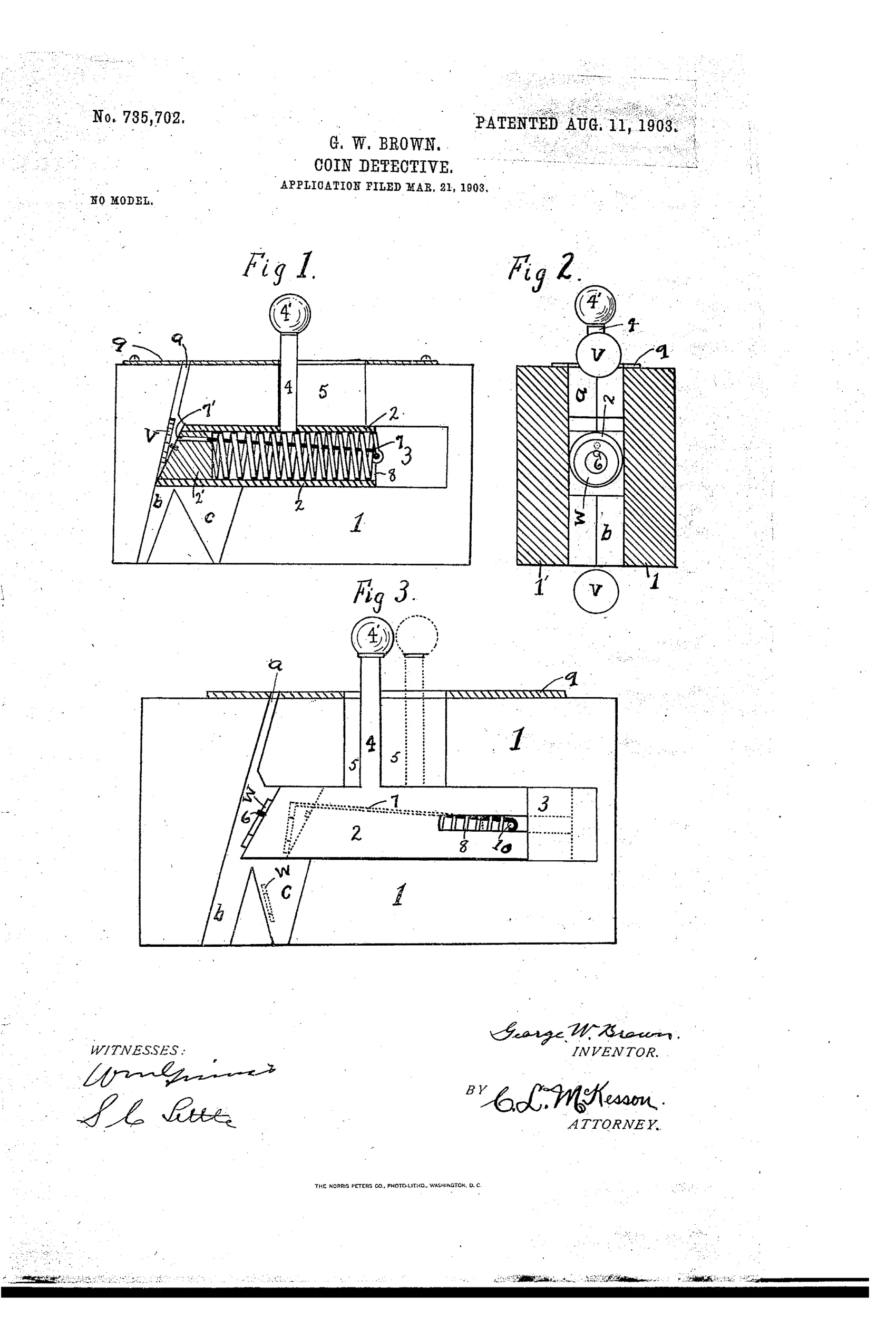
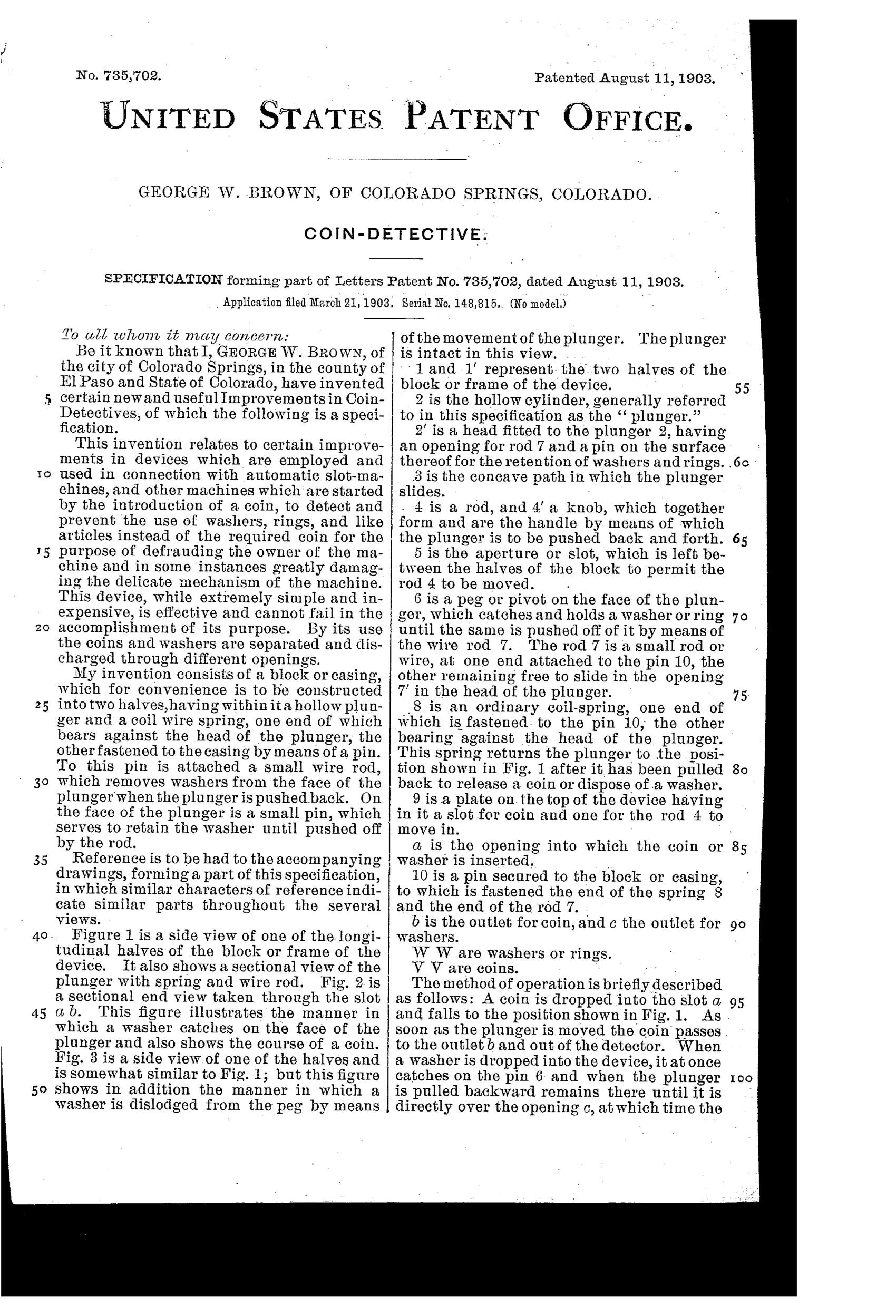
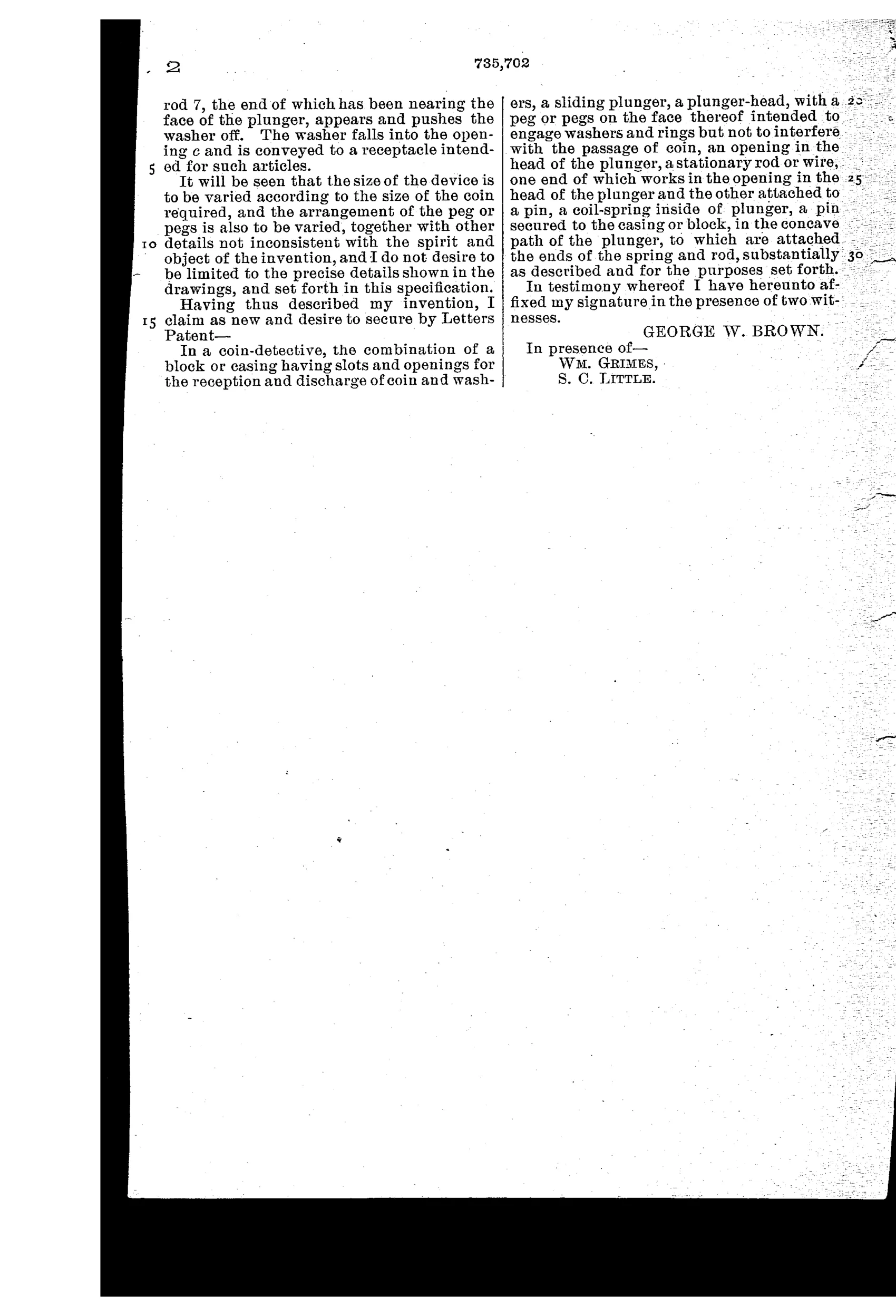
Device to detect and reject slug coins
◉ How it works
A coin or washer is dropped into a slot in a two-part block and lands in a concave path in front of a hollow sliding plunger. When the plunger is pushed back by its knob and rod, a genuine coin simply drops through to its own discharge outlet. A washer or ring instead catches on a pin projecting from the plunger's face and is carried along until, over a separate outlet, a stationary wire rod (held by an internal coil spring) reaches the plunger head and pushes the washer off the pin so it falls into its own outlet, keeping coins and slugs separated.
◉ What was claimed
“In a coin-detective, the combination of a block or casing having slots and openings for the reception and discharge of coin and washers, a sliding plunger, a plunger-head, with a peg or pegs on the face thereof intended to engage washers and rings but not to interfere with the passage of coin, an opening in the head of the plunger, a stationary rod or wire, one end of which works in the opening in the head of the plunger and the other attached to a pin, a coil-spring inside of plunger, a pin secured to the casing or block, in the concave path of the plunger, to which are attached the ends of the spring and rod, substantially as described and for the purposes set forth.”
In plain English: The patent covers a two-part slotted block with a spring-loaded sliding plunger whose head has a pin to catch washers or rings (but let coins pass) and a spring-tensioned wire rod that later pushes the caught washer off the pin so coins and slugs exit through separate openings.
◉ In the inventor’s words
“This device, while extremely simple and inexpensive, is effective and cannot fail in the accomplishment of its purpose.”— George W. Brown, from the specification
Fate unknown
No marked example or licensed use in a known vending mechanism is documented; a surviving coin chute traceable to this patent would settle it.
◉ Commentary
Most slug rejectors of this era try to measure something — weight, diameter, magnetism. Brown's idea is more literal: the commonest slug was a plain washer, and a washer has a hole in the middle. So he puts a small peg on the face of a sliding plunger. A solid coin, pushed back by the plunger, simply drops through its outlet. A washer catches on the peg by its hole and rides along until a spring-tensioned wire rod, threading through the hollow plunger, shoves it off over a second outlet. Coins here, washers there. Figure 2 is the one to study — the end section shows the washer hung on the peg like a ring on a hook.
It is a charmingly single-minded solution, and its weakness is the same as its charm: it only defeats slugs with holes. A solid disc of pot metal sails through with the honest nickels. Brown's confident boast that the device 'cannot fail in the accomplishment of its purpose' is true only if you define the purpose narrowly enough. Still, washers were cheap and everywhere, and a mechanism this simple — one plunger, one spring, one peg — could be stamped into a vending chute for pennies.
In the category's arc this sits squarely in the anonymous-chute-tester era: not a counter-top detector a shopkeeper would own, but a component looking for a machine to live inside. Whether any machine took it in, the record doesn't say.
Commentary by Claude, The Counterfeit Coin Detector Patent Archive’s resident enthusiast