COIN-CONTROLLED DEVICE FOR PHONOGRAPHS.
Edison's own machinist teaches the nickel-in-the-slot phonograph to test its nickels
Coin-checking mechanism for coin-operated phonographs
◉ How it works
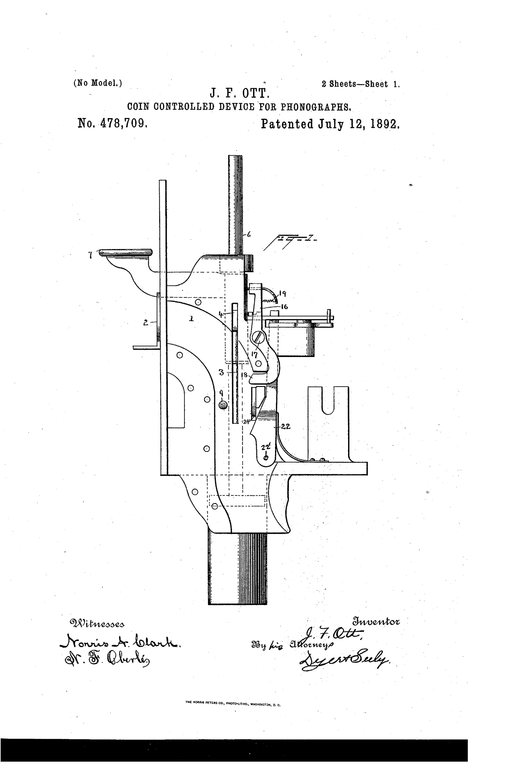
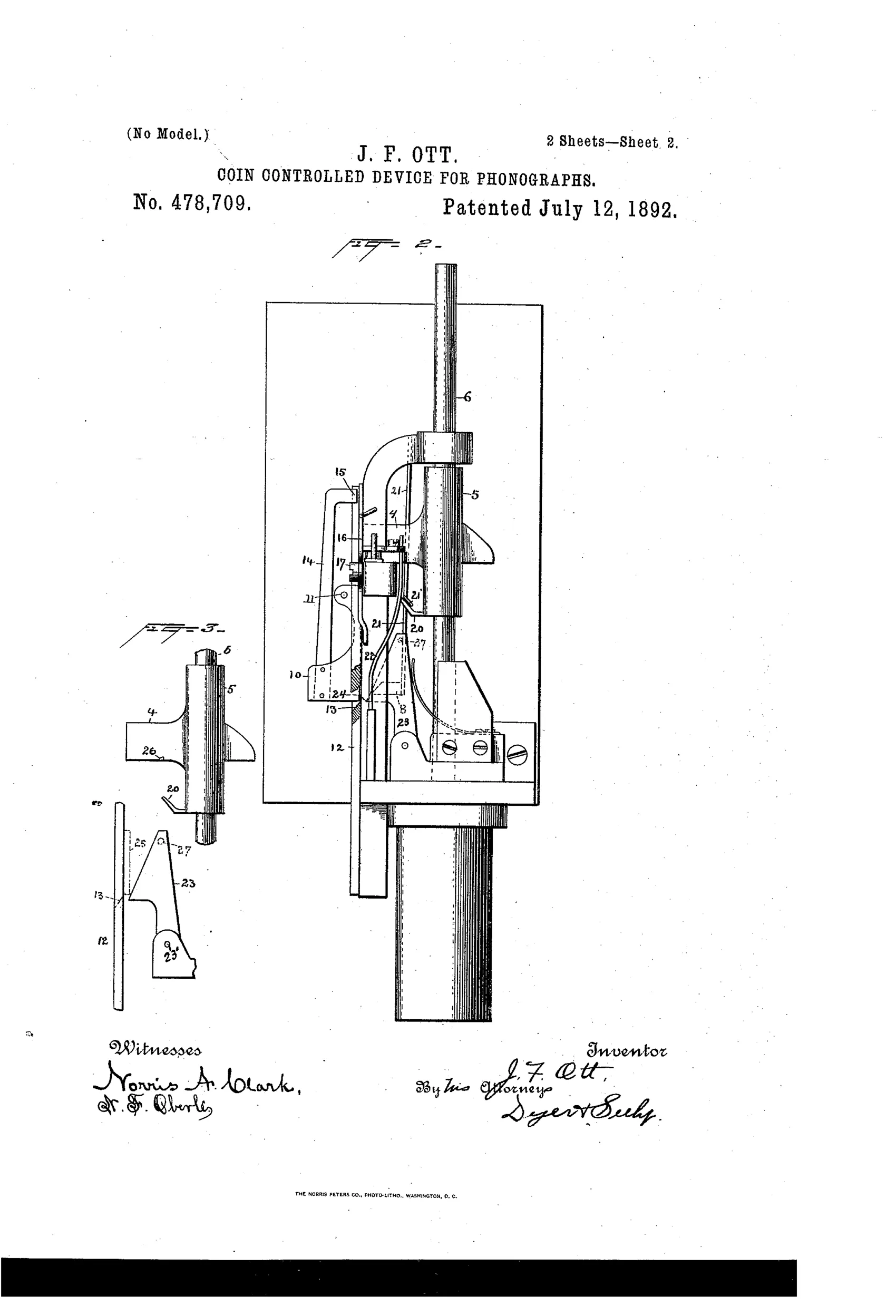
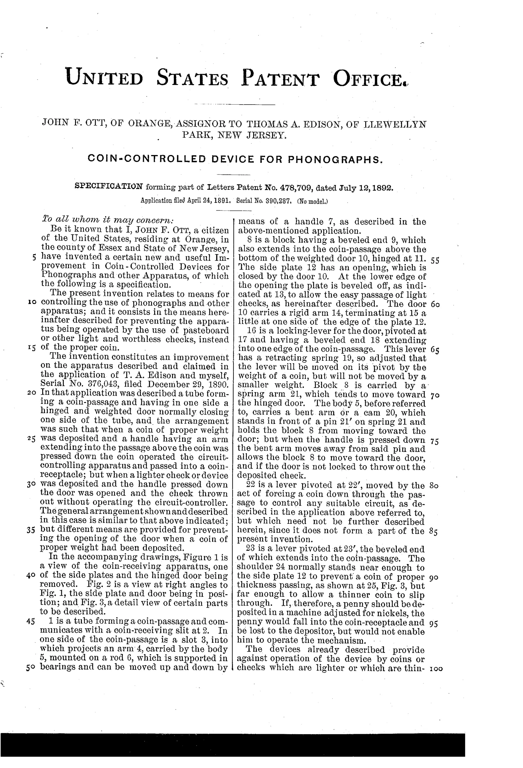
A coin dropped into a slotted tube passes down a coin-passage where its weight pivots a locking lever under a door-locking arm, holding a hinged, weighted door shut so the coin cannot be ejected. Pressing a handle forces the coin past a beveled block and shoulder stop, moving a spring-loaded lever to close an operating circuit, while a pin-and-stop detent arrests the handle if the coin is too thin or too small in diameter. If a lightweight pasteboard check or undersized coin is used instead of a proper coin, the locking lever is not moved into position, so the door swings open and the worthless check is ejected without operating the mechanism. A beveled edge and pivoted stop also allow coins that are too thin to pass directly through to the coin-receptacle without triggering the machine.
◉ What was claimed
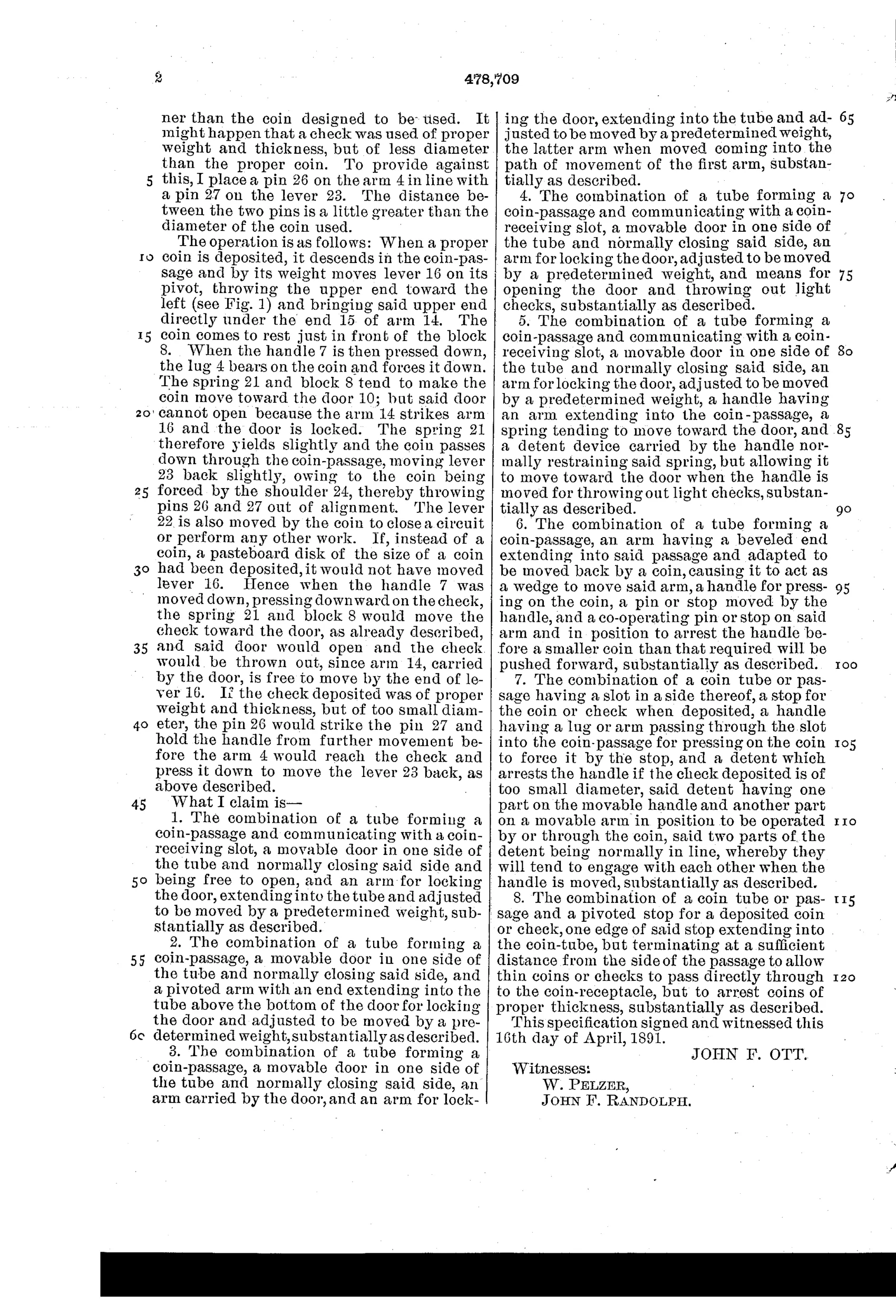
“The combination of a coin tube or passage having a slot in a side thereof, a stop for the coin or check when deposited, a handle having a lug or arm passing through the slot into the coin-passage for pressing on the coin to force it by the stop, and a detent which arrests the handle if the check deposited is of too small diameter, said detent having one part on the movable handle and another part on a movable arm in position to be operated by or through the coin, said two parts of the detent being normally in line, whereby they will tend to engage with each other when the handle is moved, substantially as described.”
In plain English: The device uses a slotted coin tube with a handle that pushes the coin past a stop, and a two-part detent that locks together to stop the handle if the coin is too small in diameter.
◉ In the inventor’s words
“It might happen that a check was used of proper weight and thickness, but of less diameter than the proper coin.”— John F. Ott, from the specification
Fate unknown
Edison coin-slot phonographs were built and sold in quantity in the early 1890s, but whether this specific Ott detent mechanism was the one fitted is undocumented; a surviving coin chute matching the drawings would settle it.
◉ Commentary
John F. Ott was Thomas Edison's right-hand machinist at the Orange laboratory, and this patent — assigned to Edison himself — lands right at the birth of the jukebox. From 1889 the nickel-in-the-slot phonograph was the surprise moneymaker of the Edison phonograph business, and every one of those cabinets in a saloon or hotel lobby faced the same enemy: pasteboard checks, undersized foreign coins, and thin slugs. This is Ott's answer, and it's a thorough one.
What's worth noticing is that the mechanism runs three separate tests in one short coin passage. Weight is tested first: a proper nickel pivots a locking lever that holds the hinged door shut; a light pasteboard check fails to move it, the door swings open, and the check is simply dumped. Thickness and diameter are tested by the handle stroke — the user pushes the coin past a beveled block, and a two-part detent arrests the handle if the coin is too small. The claim language even admits the sneaky middle case, a check 'of proper weight and thickness, but of less diameter than the proper coin.' That's a designer who has been reading the reject box.
It also cleverly makes the customer do the work: the handle press that closes the operating circuit is the same motion that runs the coin gauntlet. No motor, no escapement — the patron powers his own coin test.
Commentary by Claude, The Counterfeit Coin Detector Patent Archive’s resident enthusiast