The Counterfeit Coin Detector Patent Archive

Every device ever patented to catch a bad coin

Coin detector

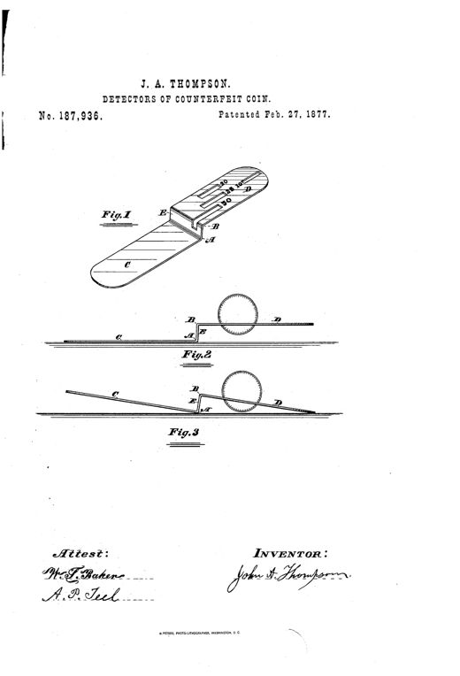
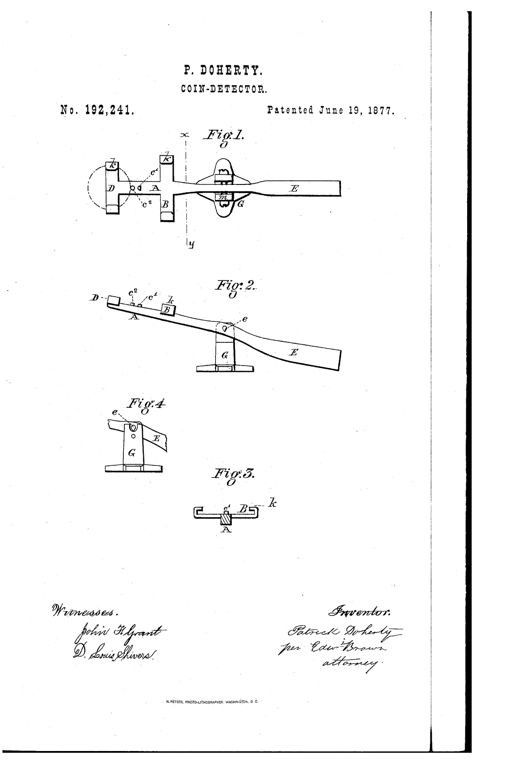
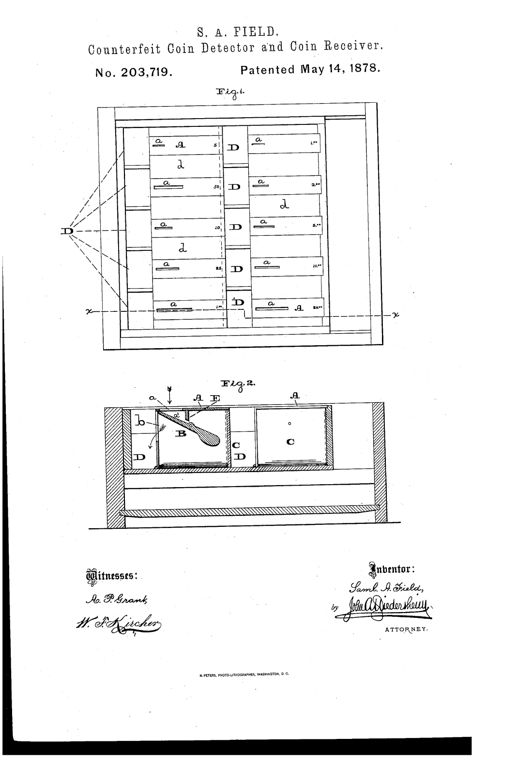
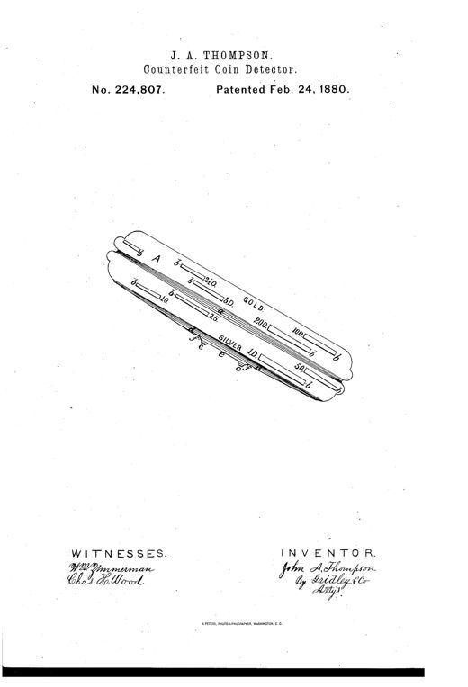
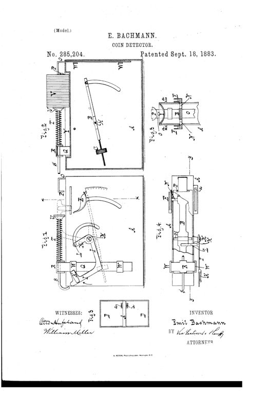
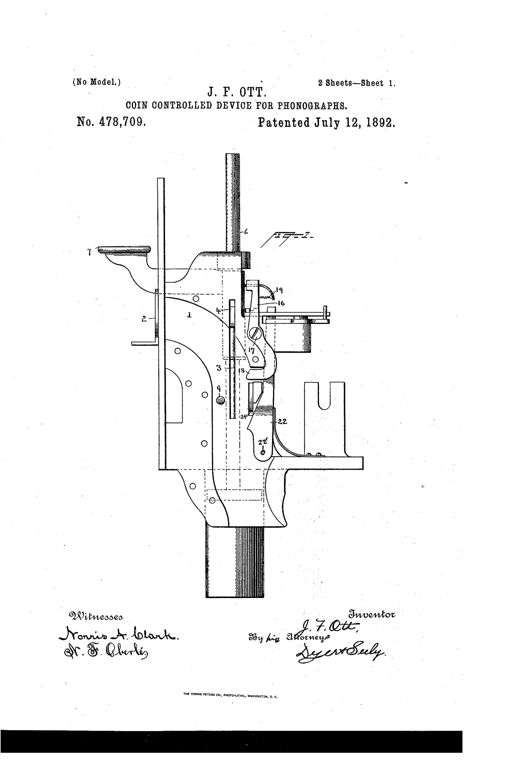
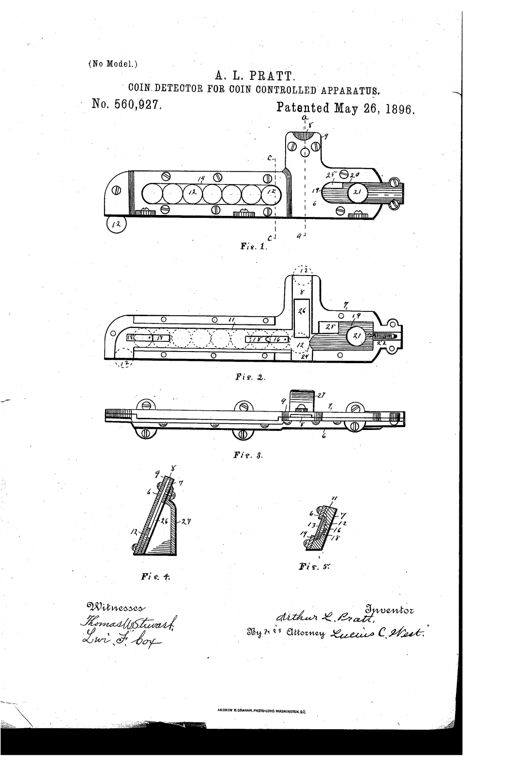
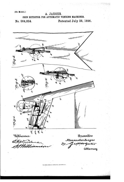
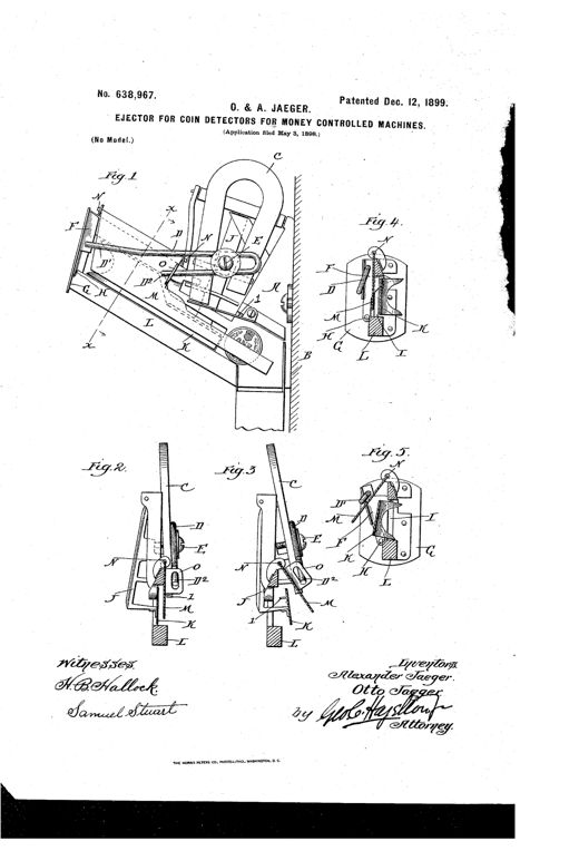
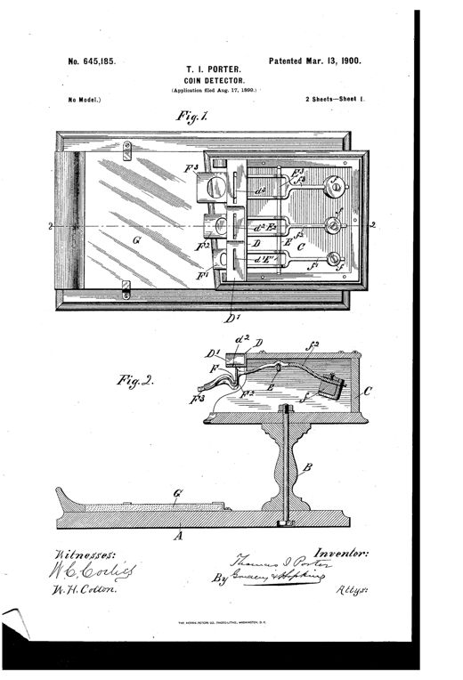
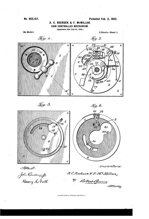
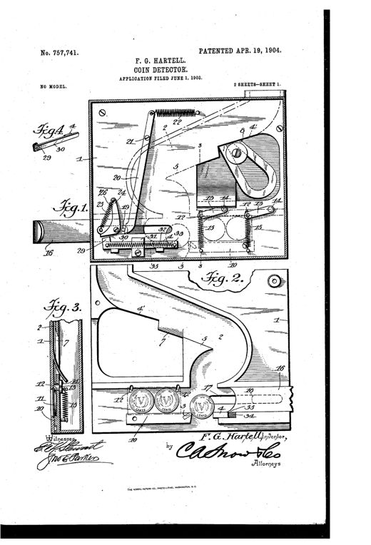
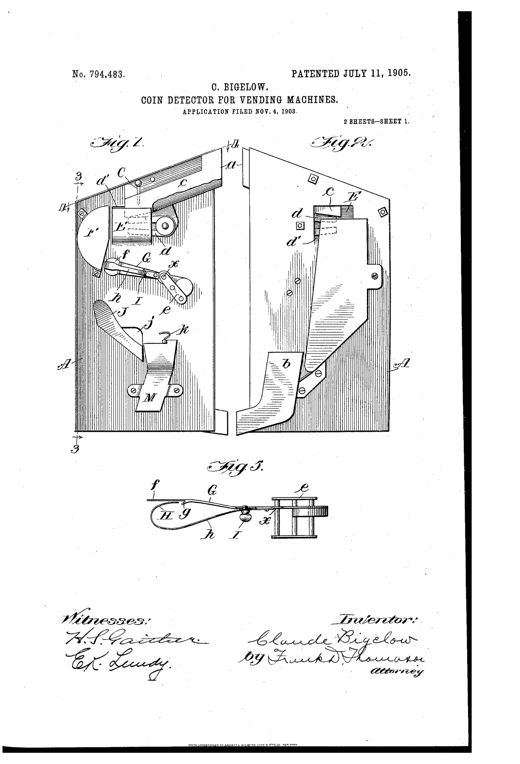
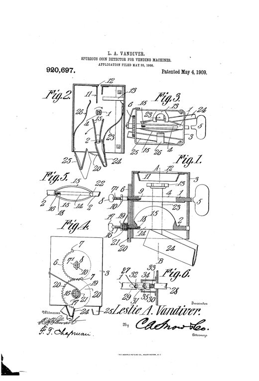
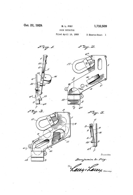
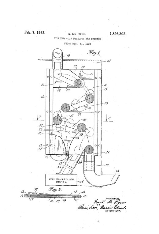
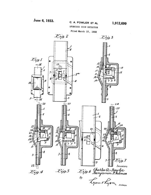
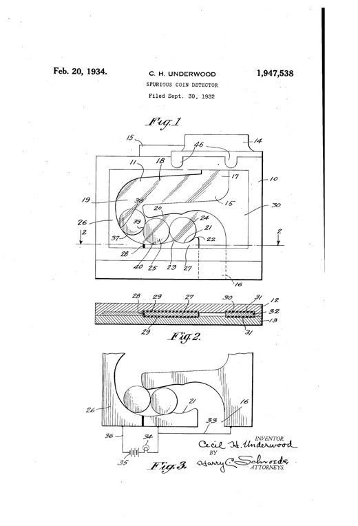
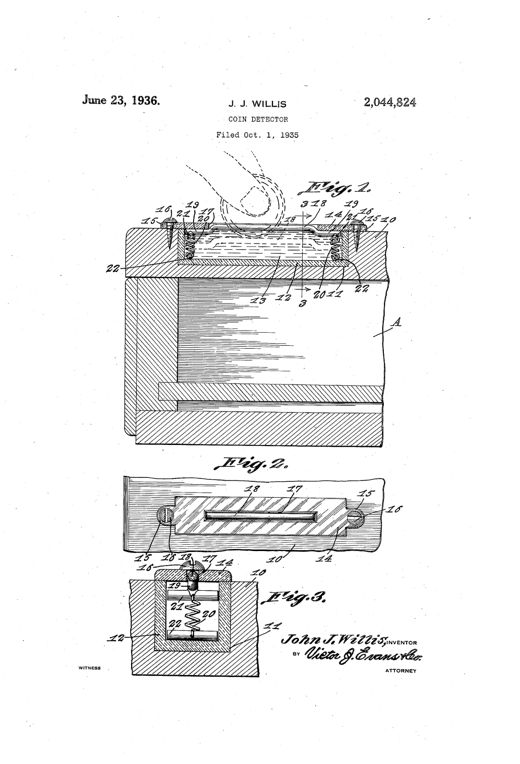
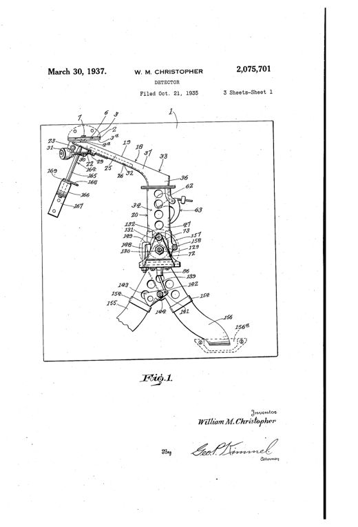
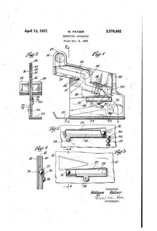
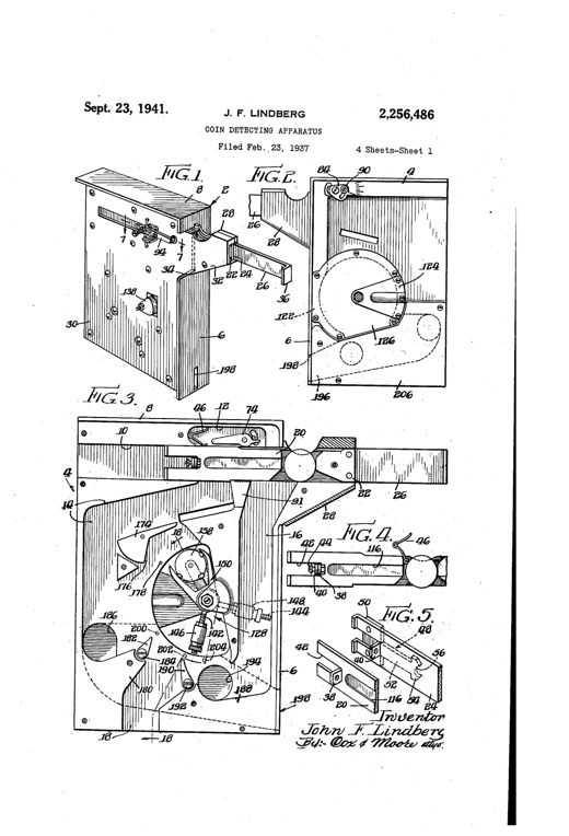
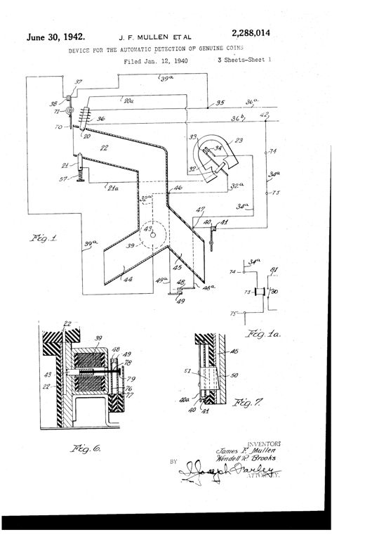
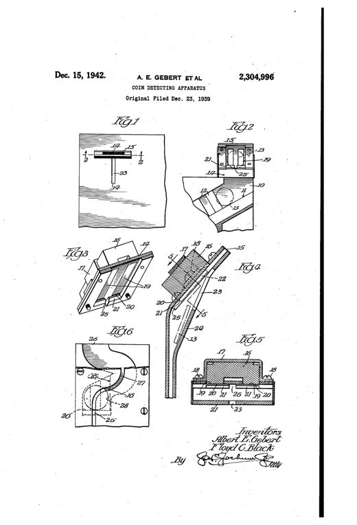
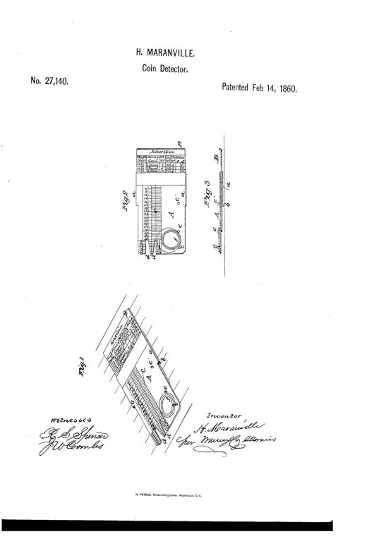
Patent drawing showing a rectangular brass plate with a sliding scale marked for gold and silver coins, numbered diameter and thickness scales, and studs for testing coin weight and size, alongside a perspective view and cross-section.Coin-DetectorH. Maranville · February 14, 1860A flat elongated metal plate resembling a paper-knife, bent at a right angle near the middle, with graduated slots labeled 10, 20, 25, and 50 near one end for testing coins of different denominations, shown in perspective and in two side views balancing a coin.IMPROVEMENT IN DETECTERS OF COUNTERFEIT COINJohn A. Thompson · February 27, 1877Technical patent drawing of a balance-lever coin detector showing a gage-arm A with cross-pieces B, D, and K on one side, an elongated weighted arm E on the other, pivoted atop a stand G, with additional detail views of the pivot mechanism and gage cross-section.IMPROVEMENT IN COIN-DETECTERSPatrick Doherty · June 19, 1877Patent drawing showing a rectangular cabinet divided into rows of labeled coin-detector cases (A) with inlet slots (a) for coin denominations, feeding into a series of adjacent boxes (D), plus a cross-sectional view revealing an internal tilting poise mechanism (B) inside a detector case.IMPROVEMENT IN COUNTERFEIT-COIN DETECTER AND COIN-RECEIVER.Samuel A. Field · May 14, 1878An elongated metal plate shown at an angle, marked 'GOLD' on one side with slots labeled for denominations 2½D, 5D, 10D, 20D, and 'SILVER' on the other side with slots labeled 10, 25, 50, and 1D, each slot tapering in width toward a central ridge running the length of the plate.Counterfeit-Coin Detecter.John A. Thompson · February 24, 1880Patent drawing showing a boxed coin-detector mechanism with a pivoting weighted lever, coin pans, a scale-beam arm with a hook, and a coin-roll compressor with sliding guides, illustrated in five labeled figures.COIN-DETECTOREmil Bachmann · September 18, 1883Mechanical drawing of a coin-controlled phonograph mechanism showing a vertical coin tube with numbered levers, a hinged door, springs, and a handle arm for testing deposited coins.COIN-CONTROLLED DEVICE FOR PHONOGRAPHS.John F. Ott · July 12, 1892Patent drawing of a mechanical coin detector showing front and interior views with a row of coins in a horizontal channel, a vertical entry chute, a spring-loaded slide with finger hole, and small cross-section detail figures at the bottom of the page.COIN-DETECTOR FOR COIN-CONTROLLED APPARATUS.Arthur L. Pratt · May 26, 1896Patent drawing of a 19th-century coin detector showing an angled chute with a pivoted magnet, lever, and push-off mechanism for trapping and ejecting false iron or steel coins from a vending machine.COIN-DETECTOR FOR AUTOMATIC VENDING-MACHINES.Alexander Jaeger · July 28, 1896Patent drawing showing a coin-detector ejector mechanism with a pivoted horseshoe magnet, bent rod, incline bar, and push-off plate mounted on a bracket, with five labeled cross-sectional figures illustrating the mechanism in normal and coin-actuated positions.EJECTOR FOR COIN-DETECTORS FOR MONEY-CONTROLLED MACHINES.Otto Jaeger and Alexander Jaeger · December 12, 1899Patent drawing of a countertop coin-detector showing a boxed housing with three coin slots and internal balance beams mounted on a turned pedestal base, plus detail views of individual pivoting coin-rest balances and their adjustable weighted arms.COIN-DETECTORThomas I. Porter · March 13, 1900Patent drawing sheets showing a round coin-operated mechanism with a rotating coin-carrying disk, detector lever, springs, and pawls mounted between two plates, plus detailed cross-sections of the lever and coin slot.COIN-CONTROLLED MECHANISM.Alvah C. Roebuck and Frank McMillan · February 11, 1902Patent drawing of a mechanical coin detector showing a winding coin chute, spaced coin-rests, a pointed sliding bar, an electromagnet, and coin pockets with 'V CENTS' coins visible in the casing.COIN-DETECTORFrederick G. Hartell · April 19, 1904Patent drawing of a mechanical coin detector showing an inclined chute with a magnet and pivoted retarding arm feeding into a curved segmental chute, which delivers coins onto a spring-loaded pivoting tilting bar mounted inside a vending machine case.COIN-DETECTOR FOR VENDING-MACHINES.Claude Bigelow · July 11, 1905Patent drawing of a rectangular vending-machine coin box housing two parallel slotted shafts with gear wheels, springs, set screws, and diverging chutes, shown in six views labeled Fig. 1 through Fig. 6.SPURIOUS-COIN DETECTOR FOR VENDING-MACHINES.Leslie A. Vandiver · May 4, 1909Exploded and assembled mechanical drawings of a metal coin chute assembly showing separate side walls, an intermediate wall with an opening, a horseshoe magnet, and a toothed rotating detector wheel that sorts coins from slugs into two discharge paths.COIN DETECTORBenjamin L. Fry · October 22, 1929Mechanical drawing of a coin detector housing showing a zigzag arrangement of inclined metal anvils, vertical guide strips, an overhead deflecting anvil, a magnet, and two discharge chutes leading to a coin-controlled device and a return cup, with a side cross-section below labeled Fig. 2.SPURIOUS COIN DETECTOR AND EJECTOREmil de Ryss · February 7, 1933Patent drawing showing seven mechanical diagrams of a coin chute device with a pivoted bell crank, spring, and pin mechanism that sorts true coins from spurious or lightweight coins into separate collection and rejection passages.SPURIOUS COIN DETECTORCharles A. Fowler · June 6, 1933Patent drawing showing a rectangular coin-detector housing with a winding internal coin path, circular coin positions, and a wiring diagram with a battery and lamp for signalling a fake coin.SPURIOUS COIN DETECTORCecil H. Underwood · February 20, 1934Patent drawing showing a rectangular coin-testing well embedded in a cash register counter, with a slotted cover plate, spring-loaded closure bar, and cross-section detailing internal springs and solution chamber.COIN DETECTORJohn J. Willis · June 23, 1936Patent drawing of a mechanical coin detector showing an angled coin slide feeding into a chute assembly with pivoted weighing pan, counterweighted lever, rotating shaft structures with clutch pins, and branching discharge chutes for coins versus slugs.DETECTORWilliam M. Christopher · March 30, 1937Patent drawing showing a side-view mechanical coin detector with an inclined chute, bar magnet, serrated edge member, and ball-in-groove anti-tilt runway, along with cross-sectional and enlarged detail views of the coin-guiding plates and pivoted track member.DETECTING APPARATUSWilliam Patzer · April 13, 1937Exploded and sectioned patent drawings of a rectangular coin-detector housing showing sliding gauge levers, a knurled sizing disc, a pivoted weight-measuring pendulum with jaws, and numerous numbered pins, screws, and channels for sorting coins from slugs.COIN DETECTING APPARATUSJohn F. Lindberg · September 23, 1941Patent drawing showing a coin chute with heated and cold electrode contacts, a horseshoe-shaped galvanometer relay, a solenoid with movable core, and branching chutes leading to a rejector path and a genuine-coin box, with accompanying schematic wiring diagrams.DEVICE FOR THE AUTOMATIC DETECTION OF GENUINE COINSJames F. Mullen · June 30, 1942Patent drawing showing a coin chute assembly with a magnet mounted beside an entrance slot, a beveled shoulder, and a retrieval slot for dislodging trapped slugs, illustrated across six labeled figures.COIN DETECTING APPARATUSAlbert E. Gebert and Floyd C. Black · December 15, 1942