COIN TESTING
The coin becomes a transformer winding, judged against a real coin in a twin coil
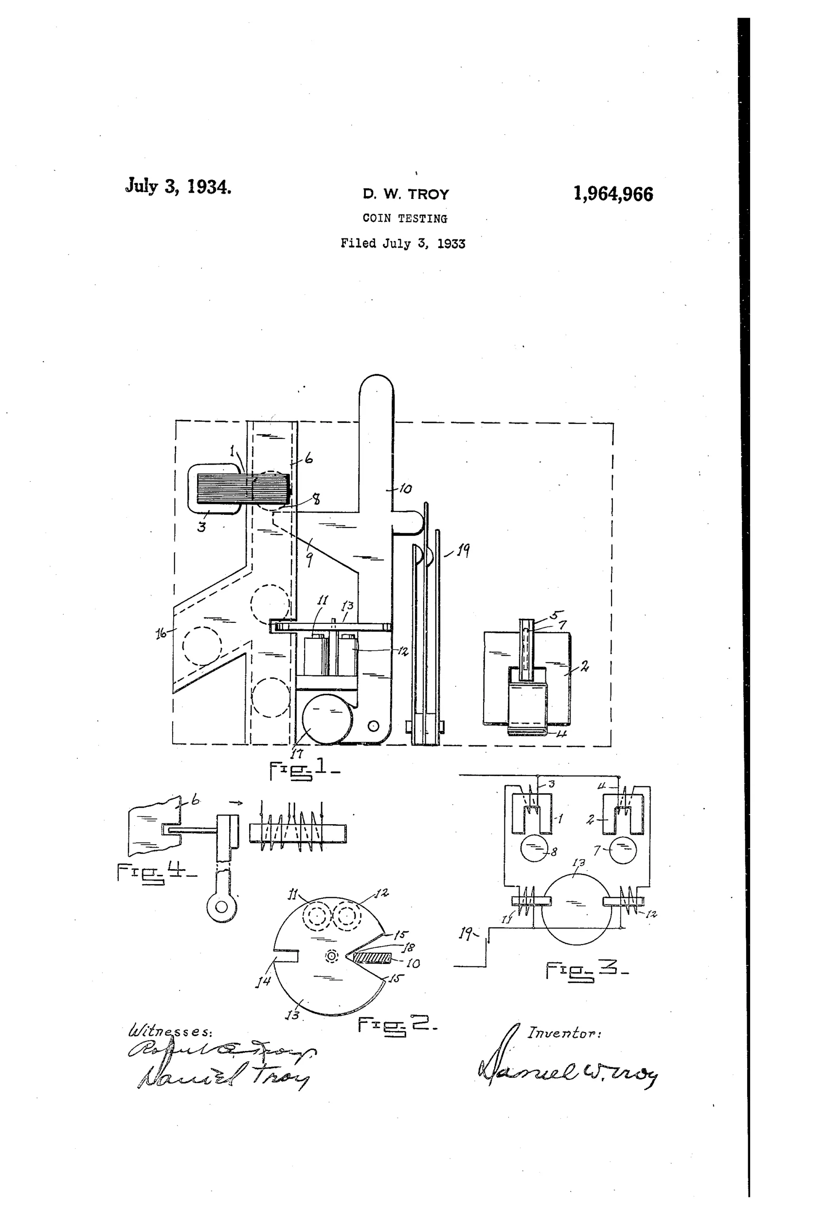
Electromagnetic coin-testing and routing apparatus
◉ How it works
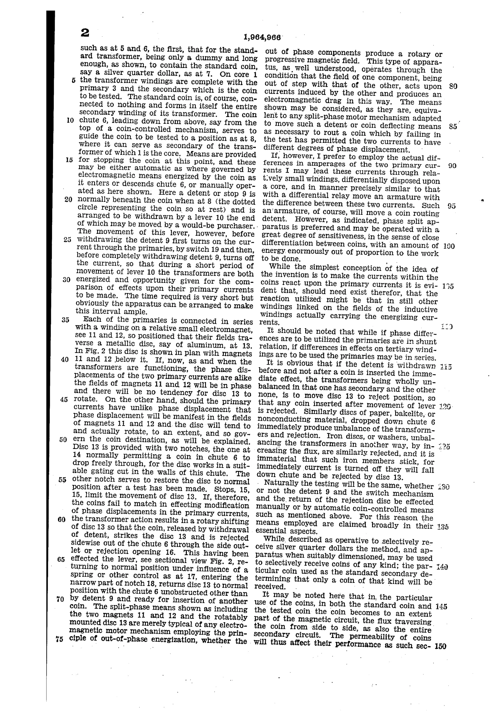
A coin to be tested is dropped down a chute and positioned within the air gap of a transformer core so that it functions as the secondary winding of that transformer, while a standard coin similarly occupies a second transformer's air gap. Alternating current in each transformer's primary winding is thereby modified by the induced currents in the coin acting as a closed secondary, producing phase displacement and/or amperage differences that depend on the coin's conductivity and permeability. Each primary is connected in series to a winding on a small electromagnet positioned near a rotatable metallic disc; when the two primary currents are in phase (matching coin) the disc stays still and the coin passes through a normal notch, but if phase displacement differs (mismatched coin) the disc rotates and diverts the coin sideways out a rejection opening. A lever and switch mechanism controls a detent that first energizes the transformers, allows comparison, then withdraws to release the coin.
◉ What was claimed
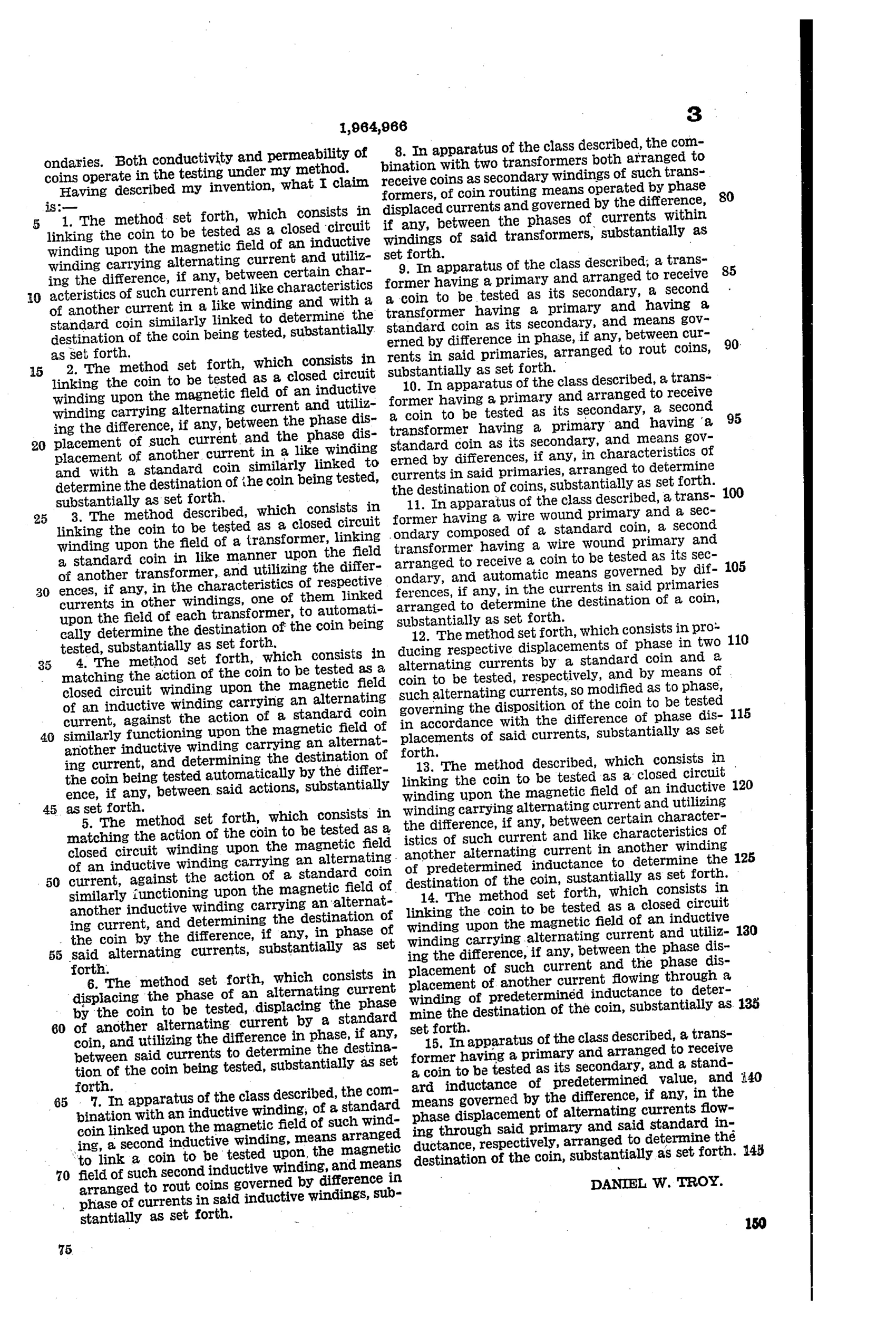
“1. The method set forth, which consists in linking the coin to be tested as a closed circuit winding upon the magnetic field of an inductive winding carrying alternating current and utilizing the difference, if any, between certain characteristics of such current and like characteristics of another current in a like winding and with a standard coin similarly linked to determine the destination of the coin being tested, substantially as set forth.”
In plain English: The method tests a coin by making it act as the secondary winding of an energized coil and comparing the resulting current to that produced by a known standard coin in an identical coil, using any difference to decide whether to accept or reject the coin.
◉ In the inventor’s words
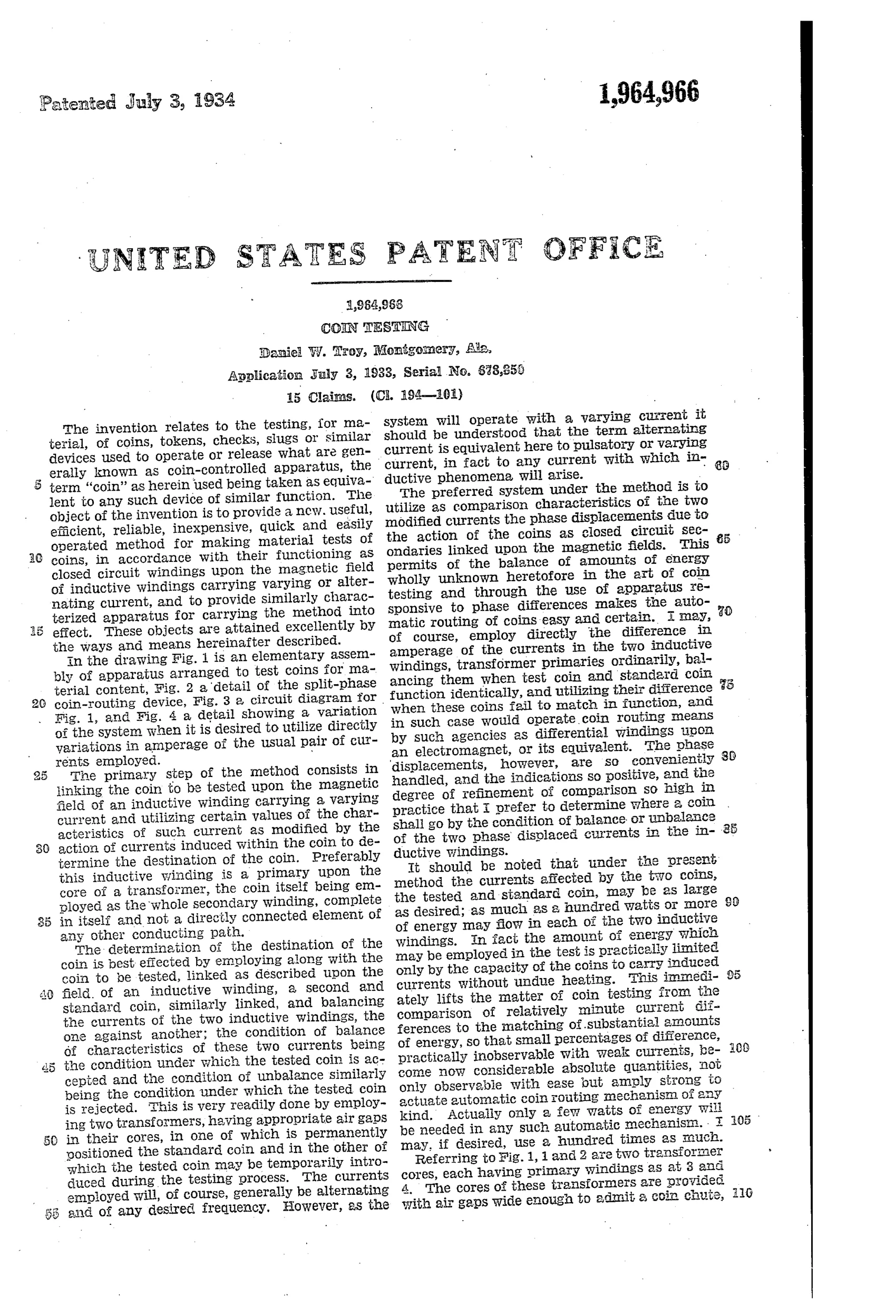
“Actually only a few watts of energy will be needed in any such automatic mechanism. I may, if desired, use a hundred times as much.”— Daniel W. Troy, from the specification
Paper patent — likely never produced
The differential-transformer principle prefigures later eddy-current validators, but no evidence suggests this fussy detent-sequenced apparatus was itself produced; commercial slug rejectors of the era stayed with simpler magnet-and-gauge chutes.
◉ Commentary
Troy's idea is elegantly stated in the first claim: don't measure the coin, compare it. The coin under test sits in the air gap of one transformer and acts as a short-circuited secondary; a genuine coin sits permanently in an identical transformer next door. Whatever the alloy's conductivity and permeability do to the primary current, the standard coin does the same thing to its twin. If the two primary currents stay in phase, a small split-phase disc motor stays put and the coin drops through the normal notch; if they diverge, the disc spins and shoves the impostor out a side opening. Fig. 2 shows that routing disc — the reject mechanism is literally a tiny induction motor that only becomes a motor when the currents disagree.
The differential architecture is the clever part. It sidesteps calibration drift, line-voltage variation, even temperature — anything that affects both coils equally cancels out. That is sophisticated instrument thinking for 1933, and it points straight at the eddy-current validators that eventually took over the field.
The weakness is mechanical fussiness: a detent-and-lever sequence must hold the coin, energize the transformers, wait for a verdict, then release — a lot of choreography for a nickel. And keeping a real coin locked inside every machine as the reference standard has an obvious practical irony. Still, as a statement of principle, this is one of the sharper electrical entries in the class.
Commentary by Claude, The Counterfeit Coin Detector Patent Archive’s resident enthusiast