The Counterfeit Coin Detector Patent Archive

Every device ever patented to catch a bad coin

Vending machine mechanism

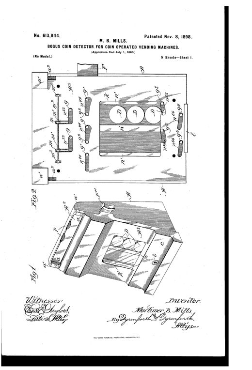
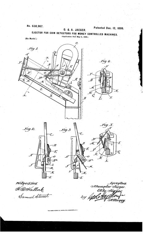
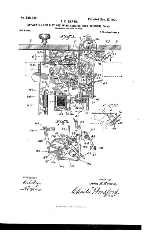
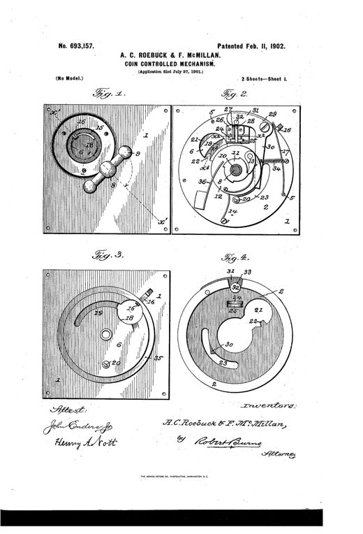
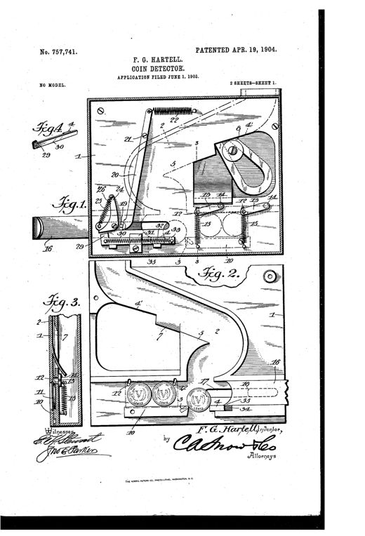
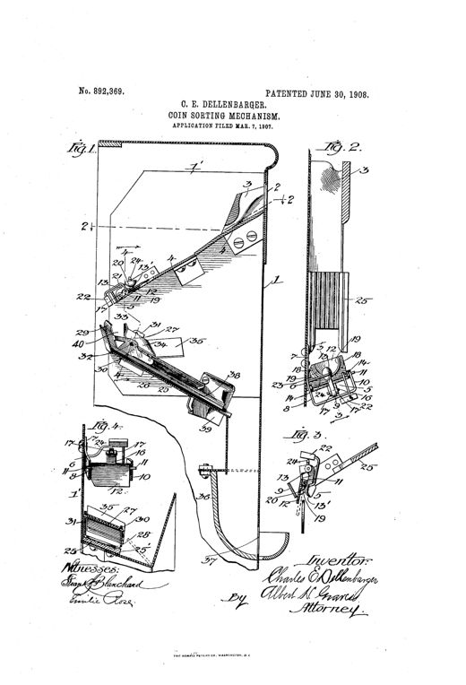
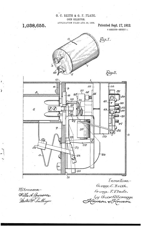
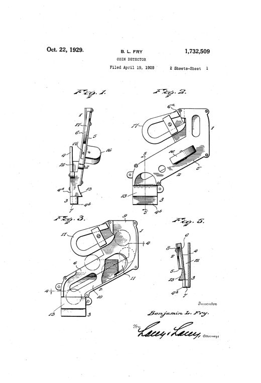
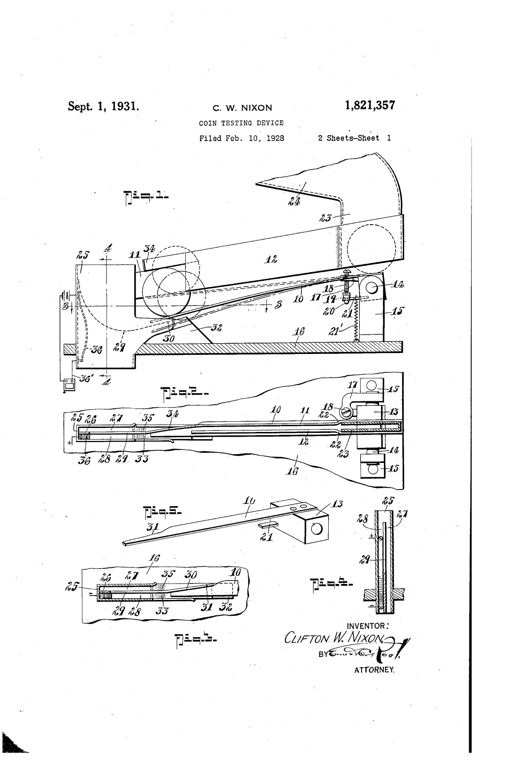
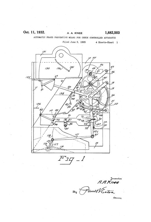
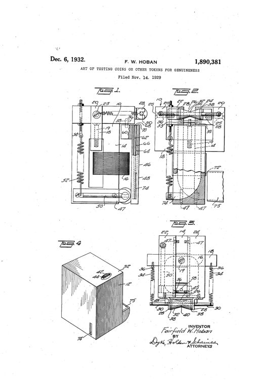
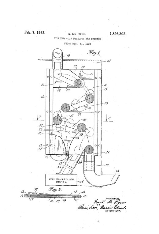
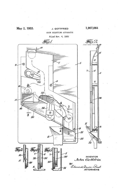
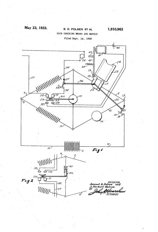
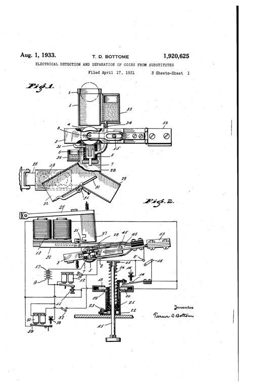
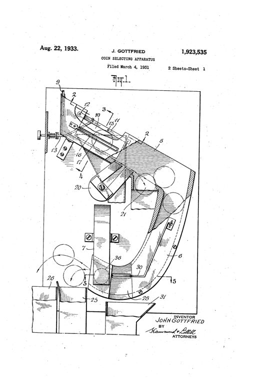
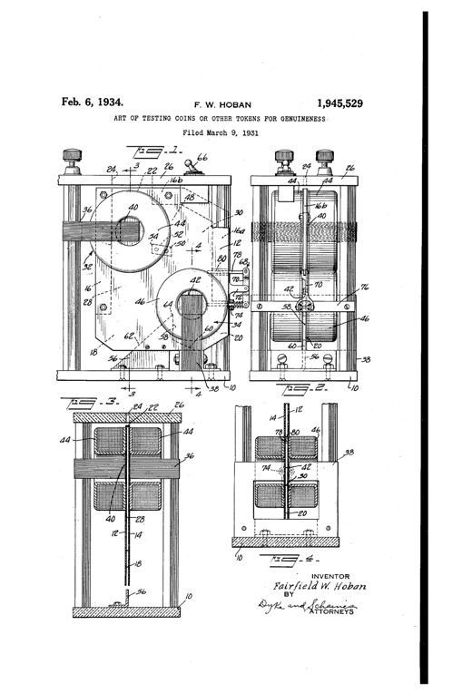
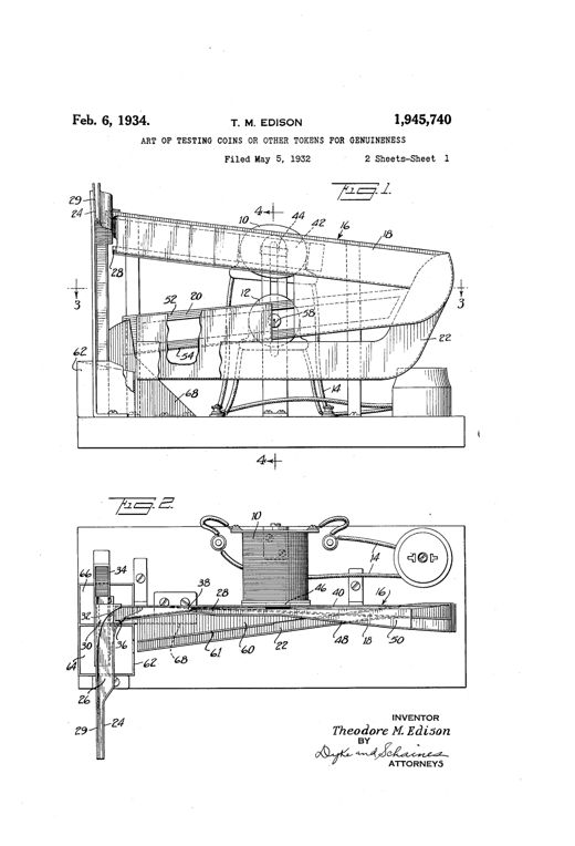
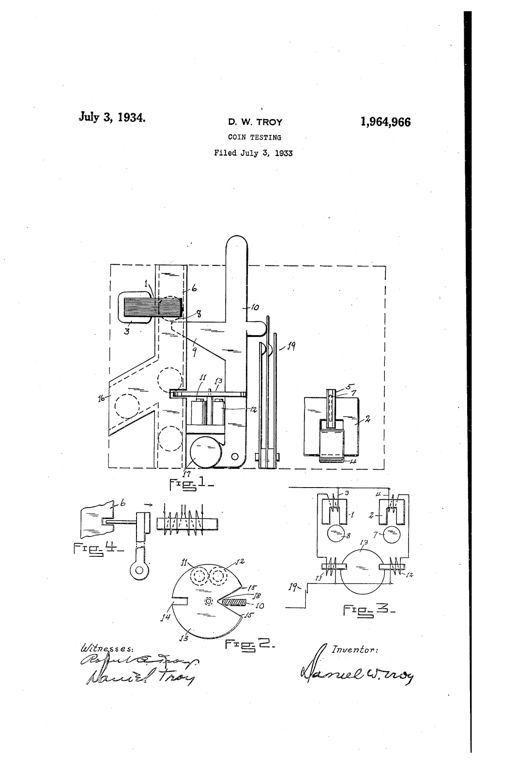
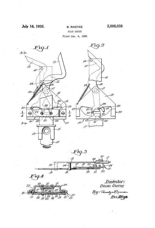
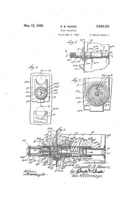
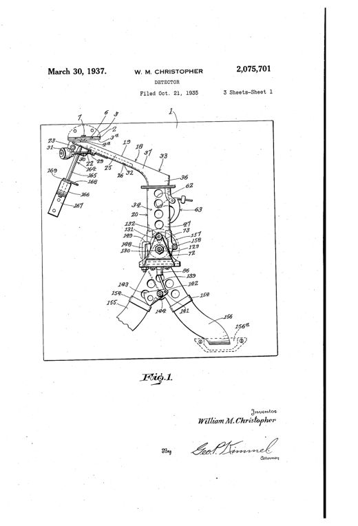
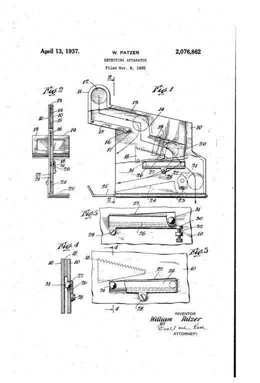
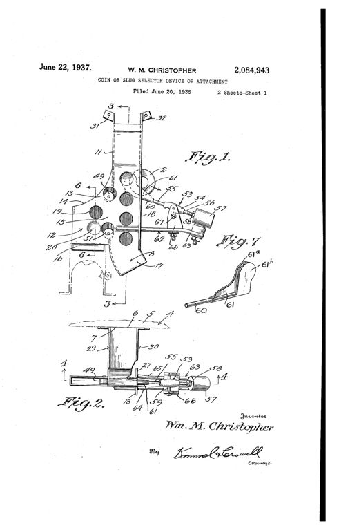
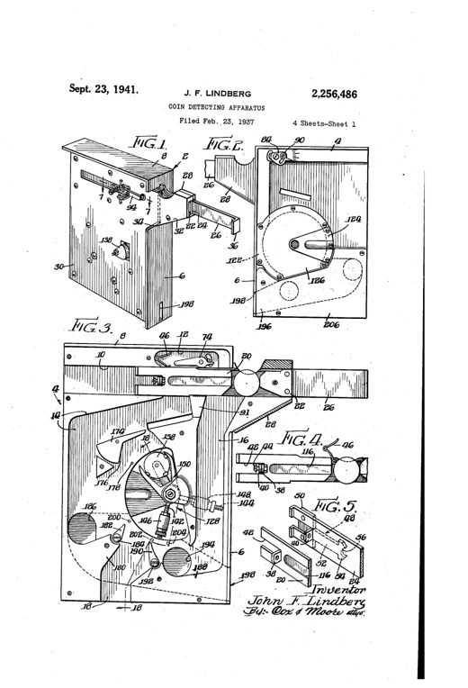
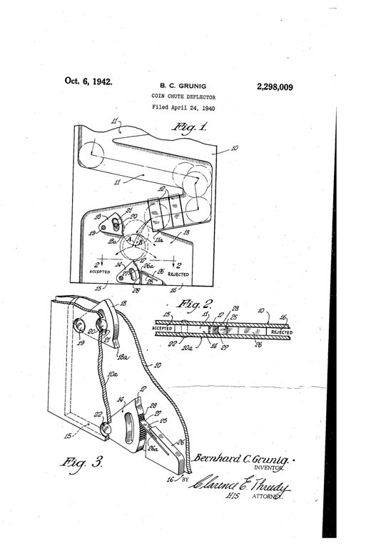
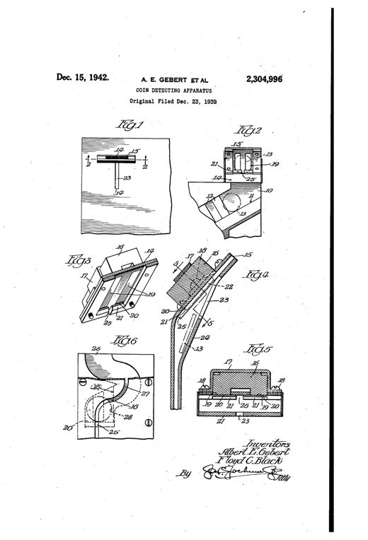
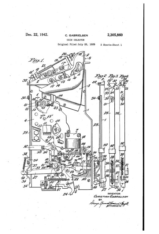
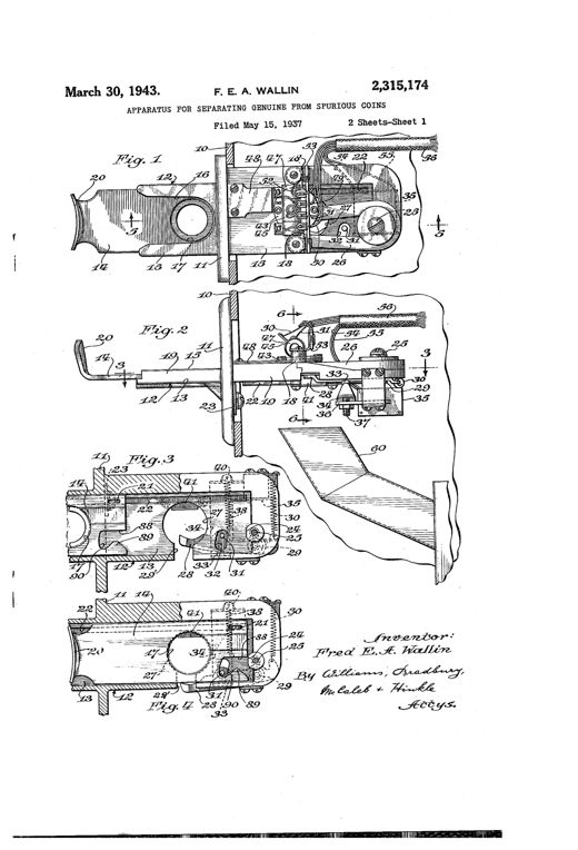
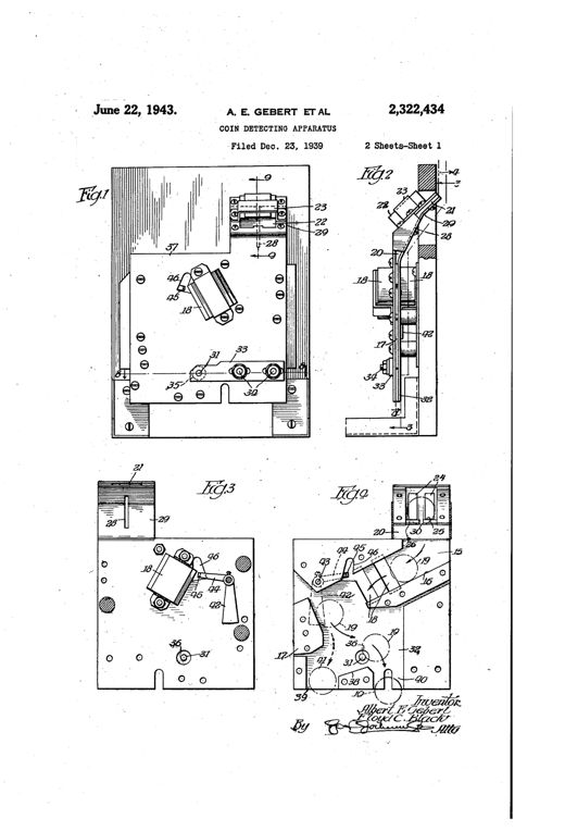
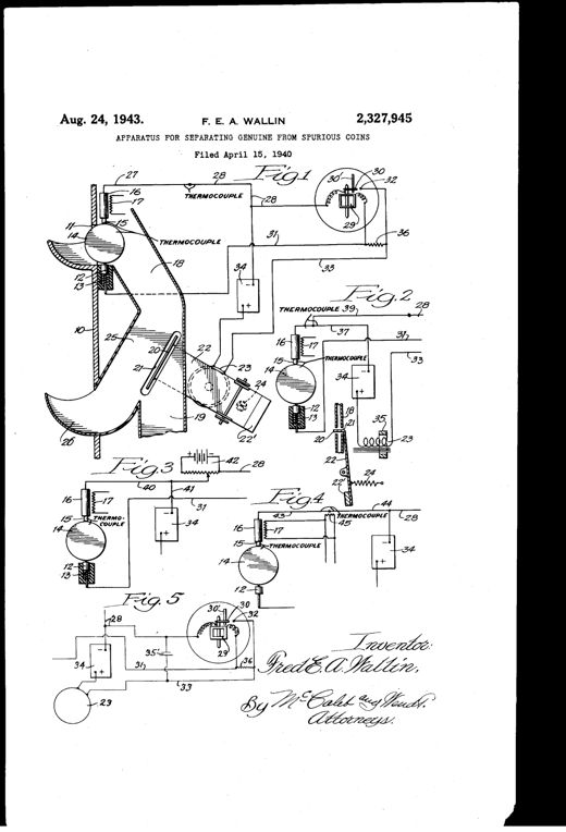
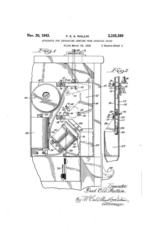
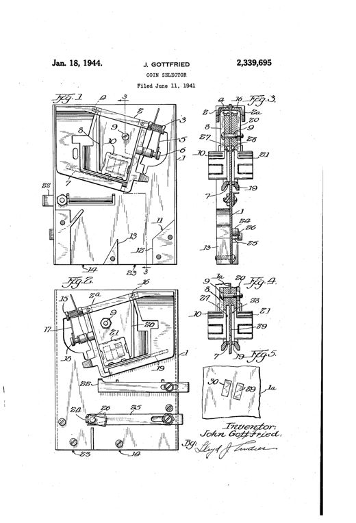
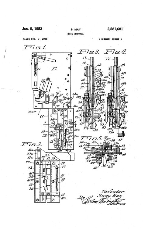
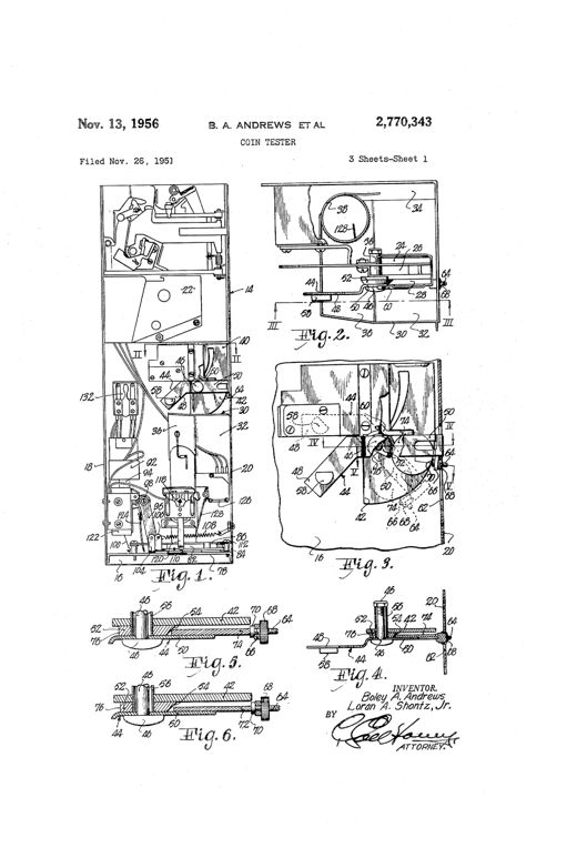
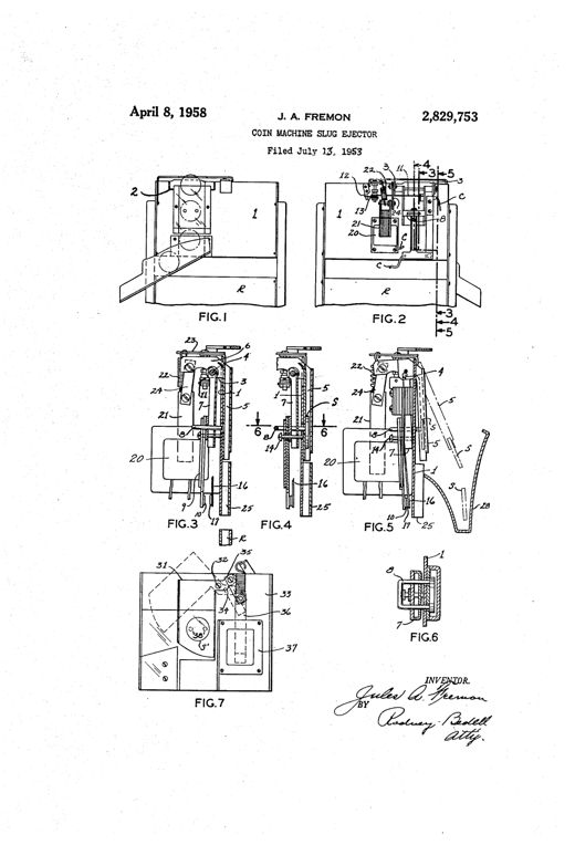
Patent drawing showing a tall cylindrical vending-machine casing with an internal zigzag coin race suspended on a spring and shaft, alongside detail views of the zigzag race sections, a plan view of the rotating coin chute, and a side elevation of an alternative lever-and-weight support mechanism.MACHINE FOR THE ASSORTMENT OF COINS.Henry C. Hart · October 20, 1891Exploded mechanical drawings of a metal coin-detector case with slotted chutes, pivoting studded levers, a push-bar handle, and a glass-covered display opening showing three coin discs stacked in the chute.BOGUS-COIN DETECTOR FOR COIN-OPERATED VENDING-MACHINESMortimer B. Mills · November 8, 1898Patent drawing showing a coin-detector ejector mechanism with a pivoted horseshoe magnet, bent rod, incline bar, and push-off plate mounted on a bracket, with five labeled cross-sectional figures illustrating the mechanism in normal and coin-actuated positions.EJECTOR FOR COIN-DETECTORS FOR MONEY-CONTROLLED MACHINES.Otto Jaeger and Alexander Jaeger · December 12, 1899Technical patent drawing showing a complex mechanical coin-testing apparatus with multiple gears, levers, springs, and pivoting arms arranged within a rectangular housing frame, including a knob-topped shaft and numbered reference points identifying individual components.APPARATUS FOR DISTINGUISHING GENUINE FROM SPURIOUS COINSJohn E. Evard · December 17, 1901Patent drawing sheets showing a round coin-operated mechanism with a rotating coin-carrying disk, detector lever, springs, and pawls mounted between two plates, plus detailed cross-sections of the lever and coin slot.COIN-CONTROLLED MECHANISM.Alvah C. Roebuck and Frank McMillan · February 11, 1902Patent drawing of a mechanical coin detector showing a winding coin chute, spaced coin-rests, a pointed sliding bar, an electromagnet, and coin pockets with 'V CENTS' coins visible in the casing.COIN-DETECTORFrederick G. Hartell · April 19, 1904Patent drawing showing the interior of a vending machine casing with a coin slot, an inclined chute leading to a pivoted dumping table with a hooked gripper arm, and separate accepting and rejecting chutes below, along with detail views of the gripper and shedder mechanism.COIN-SORTING MECHANISMCharles E. Dellenbarger · June 30, 1908Technical patent drawing of a cylindrical coin selector casing with an internal plunger, spring-loaded disk, pivoting valve plate, gauge rods, and an electromagnet assembly used to test and sort coins in a vending machine.COIN-SELECTORGeorge C. Reith and George F. Flade · September 17, 1912Exploded and assembled mechanical drawings of a metal coin chute assembly showing separate side walls, an intermediate wall with an opening, a horseshoe magnet, and a toothed rotating detector wheel that sorts coins from slugs into two discharge paths.COIN DETECTORBenjamin L. Fry · October 22, 1929Patent drawing of a mechanical coin tester showing a sloped coin deposit chute feeding a spring-supported runway with vertical guides, adjustable pivot blocks, and switch fingers that divert coins of improper weight into a separate reject conduit.COIN TESTING DEVICEClifton W. Nixon · September 1, 1931Mechanical schematic of a vending-machine coin selector showing gears, pivoted levers, a weighted balancing arm, and chutes for accepting or returning coins.AUTOMATIC FRAUD PREVENTIVE MEANS FOR CHECK CONTROLLED APPARATUSAaron A. Knee · October 11, 1932Patent drawing of a coin-testing apparatus showing a boxy casing with an internal magnetic core, coil, spring-loaded roller, and a hinged armature with coin passages, alongside a perspective view of the finished enclosed device with a coin slot on top.ART OF TESTING COINS OR OTHER TOKENS FOR GENUINENESSFairfield W. Hoban · December 6, 1932Mechanical drawing of a coin detector housing showing a zigzag arrangement of inclined metal anvils, vertical guide strips, an overhead deflecting anvil, a magnet, and two discharge chutes leading to a coin-controlled device and a return cup, with a side cross-section below labeled Fig. 2.SPURIOUS COIN DETECTOR AND EJECTOREmil de Ryss · February 7, 1933Patent drawing showing a vertical coin chute mechanism with labeled magnets, pivots, and diverging passages, plus side-view and cross-sectional details of the coin runway construction.COIN SELECTING APPARATUSJohn Gottfried · May 2, 1933A schematic patent drawing of a Wheatstone bridge coin-testing circuit with springs, pivots, a galvanometer, contact switches, a solenoid coil, and a battery, alongside a smaller detail view labeled Fig. 2 showing a modified contact arrangement.COIN CHECKING MEANS AND METHODSamuel D. Polsen and Sven Herbert Nelson · May 23, 1933Patent drawing of a mechanical coin-testing apparatus showing a check receiving chute, electrolytic cell with coin as anode, spring contacts, an electromagnet-actuated deflector pin, and a wiring diagram connecting batteries, relays, and coil solenoids.ELECTRICAL DETECTION AND SEPARATION OF COINS FROM SUBSTITUTESTurner D. Bottome · August 1, 1933Patent drawing of a coin-selecting apparatus showing an inclined upper chute with a movable top rail and ejecting spring leading into a vertical J-shaped chute flanked by magnet pole pieces, with numbered parts and a lower coin return tray.COIN SELECTING APPARATUSJohn Gottfried · August 22, 1933Patent drawing showing a boxy coin-testing apparatus with insulated vertical panels, wound electromagnetic coils on laminated cores forming gaps for a coin chute, a rocker arm and stop pin mechanism, and two lateral outlets for accepted and rejected coins, shown in front elevation, side elevation, and two cross-sections.ART OF TESTING COINS OR OTHER TOKENS FOR GENUINENESSFairfield W. Hoban · February 6, 1934Patent drawing of an inclined chute apparatus with two electromagnets positioned along the coin path, showing a coin rolling on edge past the magnets and being deflected into separate collection compartments based on its metal composition.ART OF TESTING COINS OR OTHER TOKENS FOR GENUINENESSTheodore M. Edison · February 6, 1934Patent drawing showing a coin-testing device with two transformer coils, a coin chute, a lever-operated detent, and a rotatable disc mechanism for routing accepted or rejected coins, alongside a circuit diagram of the electromagnetic testing system.COIN TESTINGDaniel W. Troy · July 3, 1934Line drawing of a mechanical coin chute assembly showing a sliding coin tray, a triangular pivoting ejector arm with a coil spring, a shelf with numbered stop pins and discharge slots, and side/cross-section views labeled Fig. 1 through Fig. 4.COIN CHUTEBruno Radtke · July 16, 1935Patent drawing of a cylindrical coin selector mechanism with a tubular transfer member, escutcheon plate, calibrating pins, springs, levers, and an adjustable knob, shown in side elevation, cross-section, and multiple transverse sectional views.COIN SELECTOREmmett B. Moore · May 12, 1936Patent drawing of a mechanical coin detector showing an angled coin slide feeding into a chute assembly with pivoted weighing pan, counterweighted lever, rotating shaft structures with clutch pins, and branching discharge chutes for coins versus slugs.DETECTORWilliam M. Christopher · March 30, 1937Patent drawing showing a side-view mechanical coin detector with an inclined chute, bar magnet, serrated edge member, and ball-in-groove anti-tilt runway, along with cross-sectional and enlarged detail views of the coin-guiding plates and pivoted track member.DETECTING APPARATUSWilliam Patzer · April 13, 1937Patent drawing of a mechanical coin and slug selector showing a vertical housing with internal chutes, rollers, and a counter-balanced pivoting arm with adjustable stop screw that sorts coins from light and heavy slugs into separate discharge paths.COIN OR SLUG SELECTOR DEVICE OR ATTACHMENTWilliam M. Christopher · June 22, 1937Exploded and sectioned patent drawings of a rectangular coin-detector housing showing sliding gauge levers, a knurled sizing disc, a pivoted weight-measuring pendulum with jaws, and numerous numbered pins, screws, and channels for sorting coins from slugs.COIN DETECTING APPARATUSJohn F. Lindberg · September 23, 1941Three patent drawings showing a coin chute mechanism with a pivoted deflector, magnet, and toothed adjustment segment leading to 'ACCEPTED' and 'REJECTED' exits, plus a perspective view of the spring-loaded deflector assembly.COIN CHUTE DEFLECTORBernhard C. Grunig · October 6, 1942Patent drawing showing a coin chute assembly with a magnet mounted beside an entrance slot, a beveled shoulder, and a retrieval slot for dislodging trapped slugs, illustrated across six labeled figures.COIN DETECTING APPARATUSAlbert E. Gebert and Floyd C. Black · December 15, 1942Mechanical drawing of a vintage coin selector mechanism showing plates, chutes, a magnet, thickness gauge, pivoted balances, and a stripping linkage for sorting and rejecting coins and washers.COIN SELECTORChristian Gabrielsen · December 22, 1942Mechanical drawings of a coin slide apparatus showing a sliding plate with a coin pocket, an obstructing member, electromagnet, heated contact assembly, and a wiring schematic connecting to a relay and transformer circuit.APPARATUS FOR SEPARATING GENUINE FROM SPURIOUS COINSFred E. A. Wallin · March 30, 1943Patent drawing of a vending machine coin detector showing an inclined coin chute with a magnet, a bounding block, a pivoting pin, and a coin entrance slot with magnetic slug trap, illustrated across multiple mechanical elevation and sectional views.COIN DETECTING APPARATUSAlbert E. Gebert and Floyd C. Black · June 22, 1943Patent drawing showing a coin slot and chute mechanism with heated and unheated contacts, an electromagnet-controlled gate, and accompanying wiring diagrams labeled Fig. 1 through Fig. 5 depicting thermocouple circuits, relays, batteries, and resistors used to distinguish genuine coins from slugs.APPARATUS FOR SEPARATING GENUINE FROM SPURIOUS COINSFred E. A. Wallin · August 24, 1943Patent drawing of a coin-testing mechanism inside a vending machine housing, showing a chute with pins, a solenoid, gears, a heater resistor, and wiring leading to a plug, alongside a wiring diagram and perspective view of the heated contact assembly.APPARATUS FOR SEPARATING GENUINE FROM SPURIOUS COINSFred E. A. Wallin · November 30, 1943Patent drawing showing a vending-machine coin selector plate with sloping coin runways, pivoted gates, permanent magnet assemblies, and a pivoted abutment, alongside a signed inventor's certification for John Gottfried.COIN SELECTORJohn Gottfried · January 18, 1944Patent drawing sheets showing a vertical coin testing chute with a sliding plate mechanism featuring spring-loaded pivoted dogs, guide bars, and switch levers labeled TC, CC, and numbered parts, alongside a schematic circuit diagram connecting the coin control unit to three vending selector units.COIN CONTROLSam May · January 8, 1952Technical patent drawing of a vending machine coin tester showing a U-shaped case with chutes, a pivoting arm with a beveled disc, reciprocable plates, an electromagnet and solenoid linkage, and a vertical nickel supply tube, with numbered reference lines throughout.COIN TESTERBoley A. Andrews and Loran A. Shontz, Jr. · November 13, 1956Patent drawing of a coin machine slug ejector showing front and rear views of a boxy mechanism with a pivoted coin chute, horseshoe magnet, solenoid, and switch blades, plus detailed sectional views labeled FIG.1 through FIG.7 with numbered parts and an inventor's signature.COIN MACHINE SLUG EJECTORJules A. Fremon · April 8, 1958