COIN OR SLUG SELECTOR DEVICE OR ATTACHMENT
One pivoting arm sorts coins three ways: too light, too heavy, just right

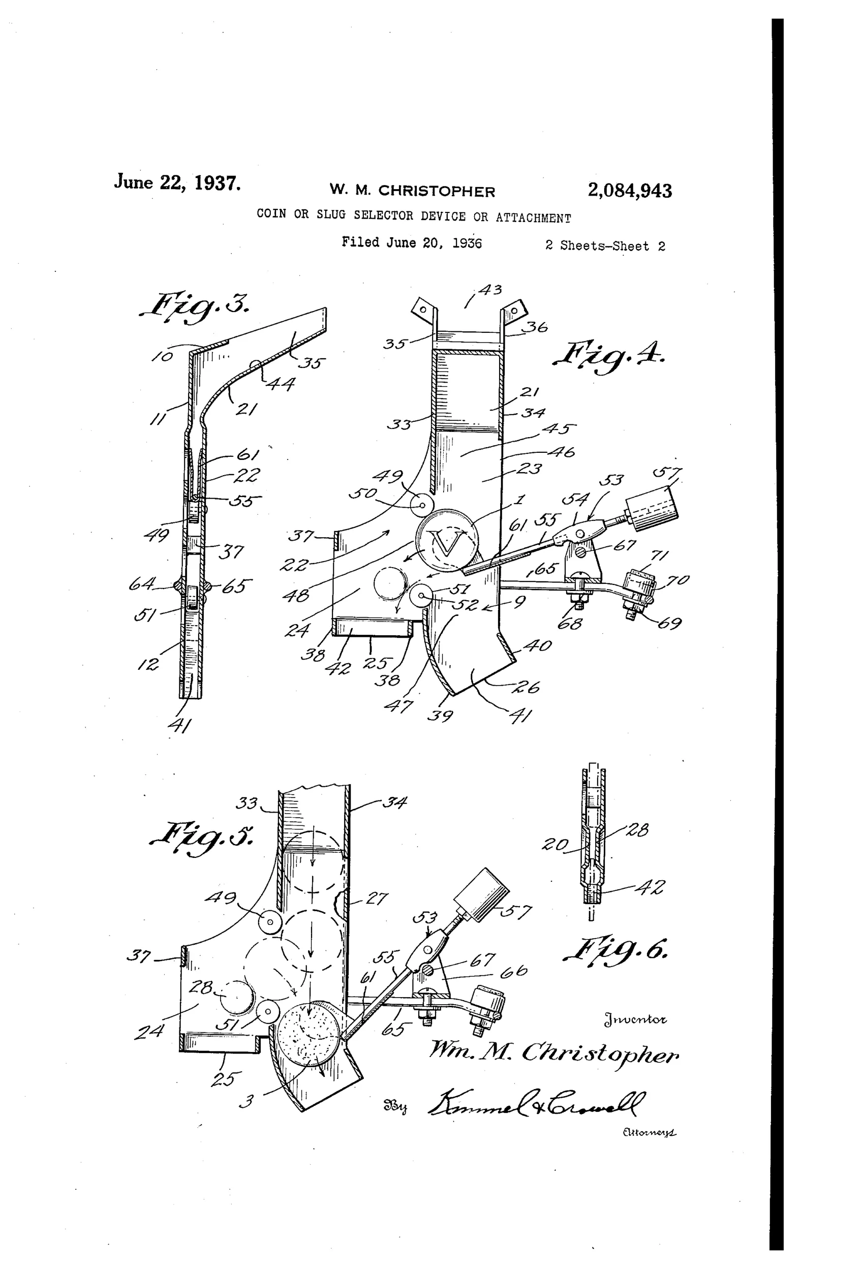
Mechanical coin/slug selector attachment for vending machines
◉ How it works
Coins and slugs entering the device travel down a common conductor passage past spaced deflector rollers. A counter-balanced, eccentrically pivoted arm carrying a combined receiver, guide and selector member sits in the path of travel; a genuine coin depresses the arm to the correct position so it is guided into a separate coin chute. A light slug fails to depress the arm and is ejected out its own outlet, while a heavy (thicker) slug depresses the arm further, riding it into a different chute that ejects the slug rather than allowing it to reach the coin outlet. An adjustable stop screw limits the downward travel of the pivoted arm to fine-tune the sizing/weight discrimination, and superposed guide rollers at the chute junctions prevent coins or slugs from wedging or centering incorrectly.
◉ What was claimed
“1. In a selector device, a conducting structure common to a coin and light and heavy slugs, said structure being formed with means to provide, respectively an outlet for the discharge of a light slug, a chute leading to an outlet for the discharge of a heavy slug, a chute leading to an outlet for the discharge of a coin, an intake and a passage communicating at spaced points with the outlet for the light slug and the chutes for the heavy slug and coin, said intake and passage being respectively common for the insertion of and for the travel of inserted coins and slugs, an eccentrically pivoted counter-balanced shiftable element supported by and extending laterally from one side of said structure through the outlet for the light slug, said element including a shaft having its inner end terminal portion provided with an upwardly and downwardly movable combined receiver, guide and selector member common to the coin and slugs, said member disposed in said passage in the path of a coin and slugs inserted in said structure and acting respectively on receiving a light slug to eject the latter through its outlet; on receiving a heavy slug to eject the latter into the chute leading to the outlet for the heavy slug and on receiving a coin for delivering the latter into the chute leading to the coin outlet, and spaced superposed aligning guide rollers at the point of communication between the coin chute and passage acting to prevent the wedging and centering of a coin and a heavy slug between the rollers and the inner end of said shaft.”
In plain English: A single shared chute funnels coins and slugs past a spring-balanced pivoting arm that senses weight/thickness, routing genuine coins to the coin outlet while diverting light slugs and heavy slugs each to their own separate ejection chutes, with rollers preventing jamming.
◉ In the inventor’s words
“It is to be understood that the attachment may be connected to the machine at any suitable point so it will coact with the coin operated mechanism or the coin controlled mechanism of the machine in a manner whereby the coin will be delivered at the desired point.”— William M. Christopher, from the specification
Fate unknown
Like most in-chute selector patents, this one carries no assignee and likely vanished into anonymous vending hardware if built at all; a marked mechanism or trade-catalog listing would settle it.
◉ More by William M. Christopher
- DETECTOR (1937)
◉ Commentary
By 1936 the slug problem had matured. Vending operators weren't just losing money to washers and blanks — they faced deliberately made slugs, some heavier and thicker than the real coin. Christopher's answer is a single counter-balanced arm that acts as a three-way switch: a light slug fails to depress it and gets pushed out its own exit, a genuine coin depresses it just enough to be steered into the coin chute, and an over-heavy slug rides the arm past the coin path into a separate reject chute. It's a Goldilocks mechanism in sheet metal, and the adjustable stop screw (visible in Fig. 1 near the eccentric pivot) lets an operator tune the sweet spot in the field.
The detail worth pausing on is the pair of superposed guide rollers at the chute junction, called out explicitly in claim 1. Anyone who has serviced coin gear knows the real enemy isn't misclassification — it's jamming. A coin that wedges between a moving arm and a fixed wall kills the machine until someone shows up with a screwdriver. Christopher clearly knew this failure mode and designed against it, which suggests practical experience rather than armchair invention.
Still, this is a refinement in a crowded decade, not a landmark. Purely gravimetric sorting can't catch a slug of correct weight but wrong metal, which is why magnetic and later electrical tests won out. It's a workmanlike entry from the era when every chute designer was chasing the same slippery target.
Commentary by Claude, The Counterfeit Coin Detector Patent Archive’s resident enthusiast