COIN-SELECTOR
A coin must close electric switches to prove itself — feeler pins as jury
Electrically-controlled coin-testing and rejecting mechanism
◉ How it works
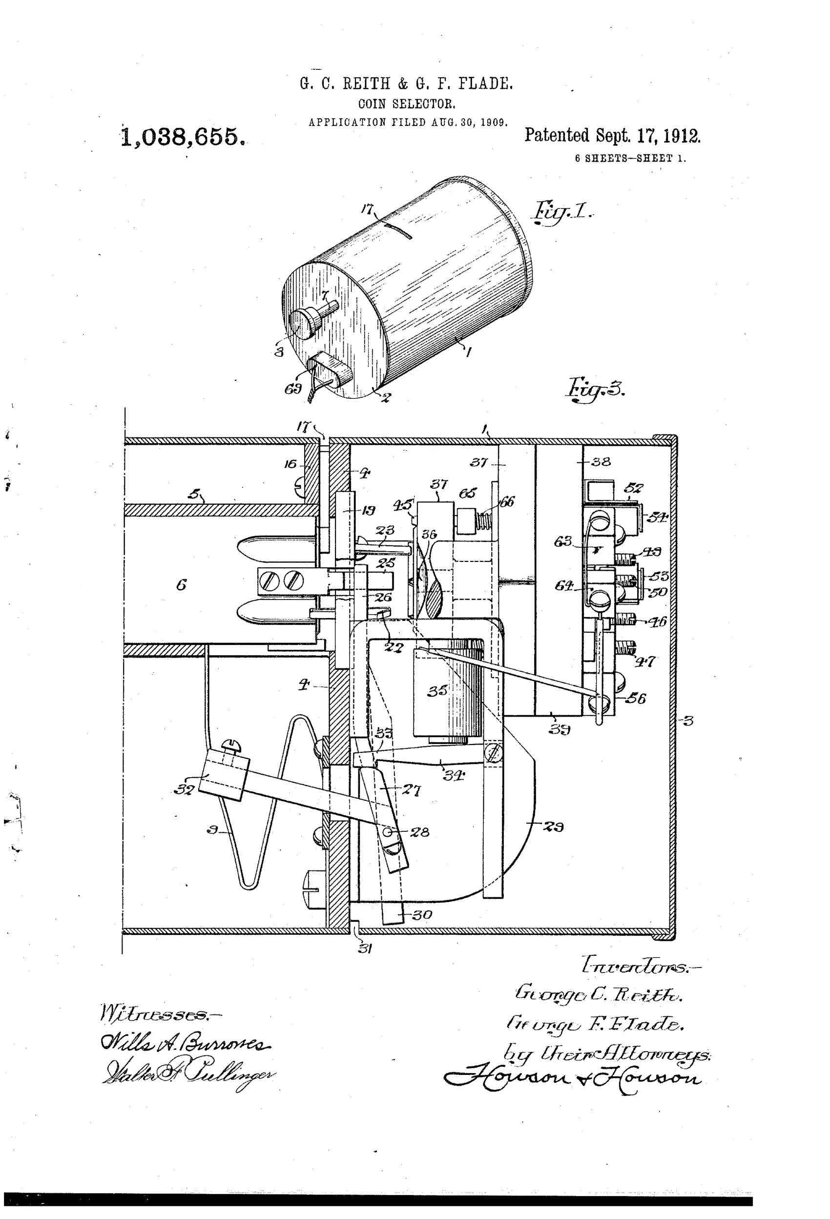
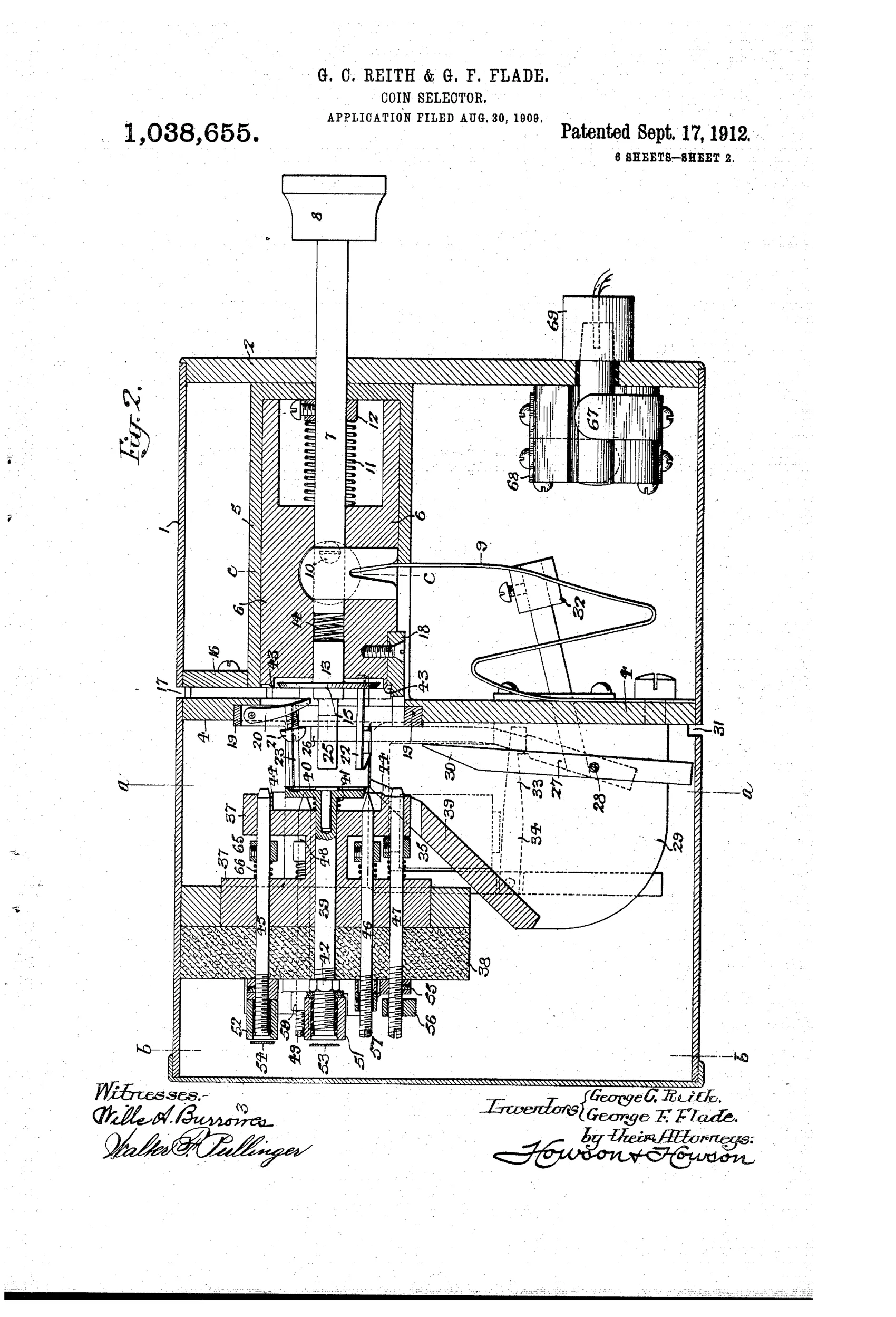
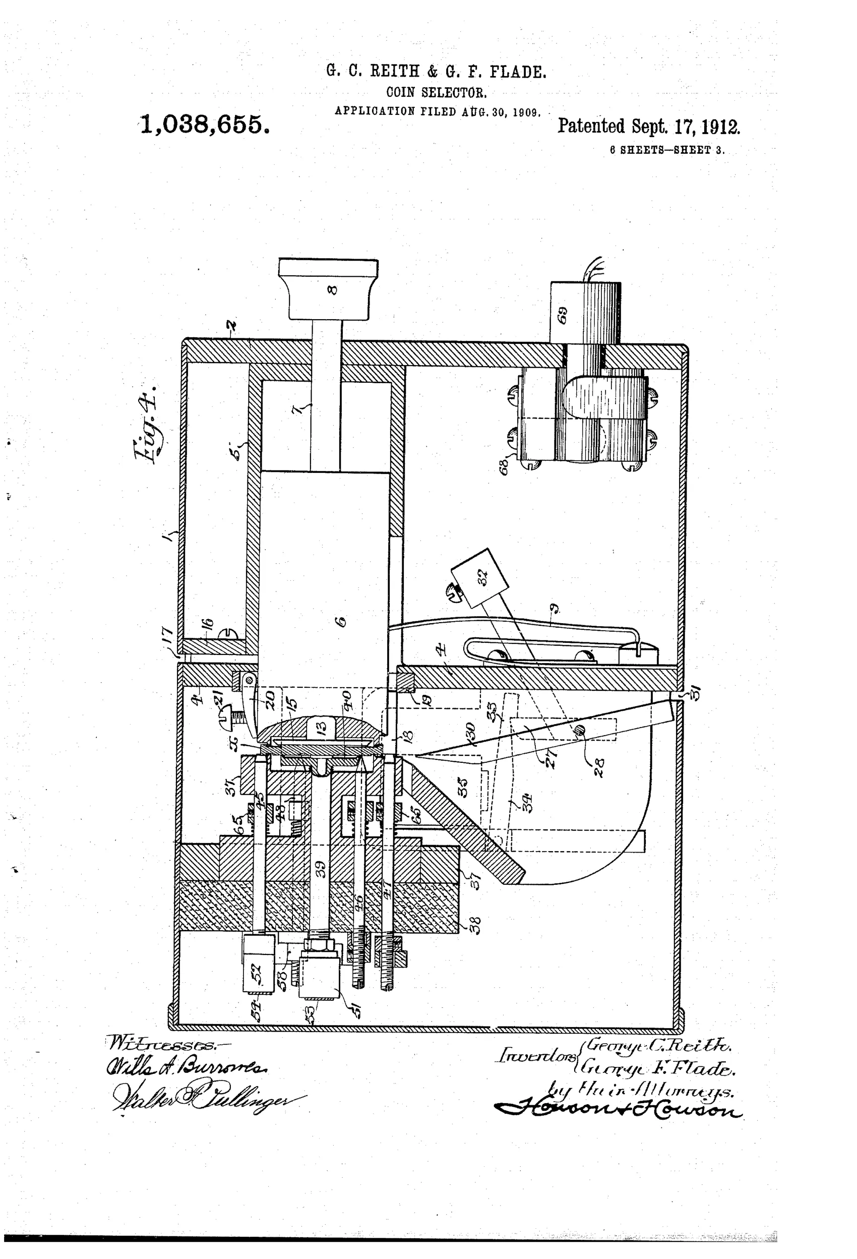
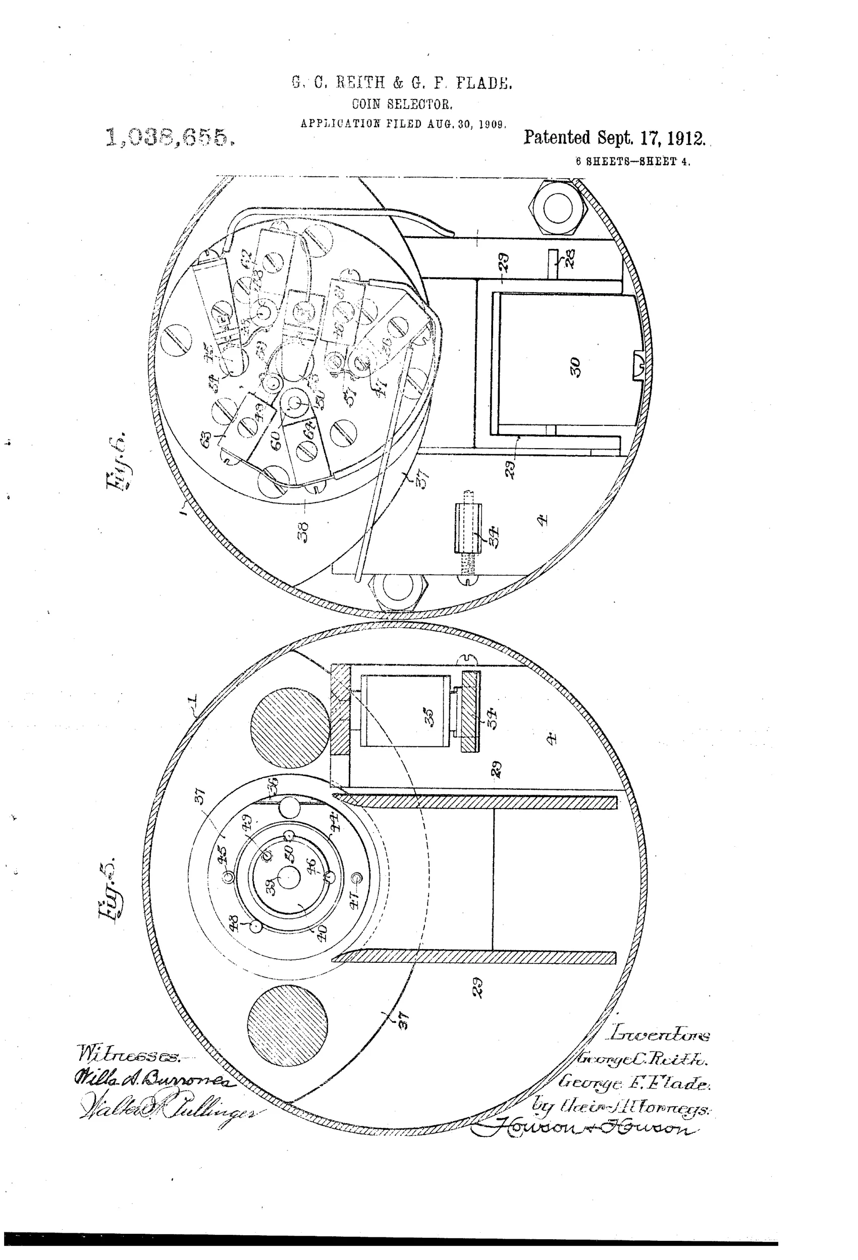
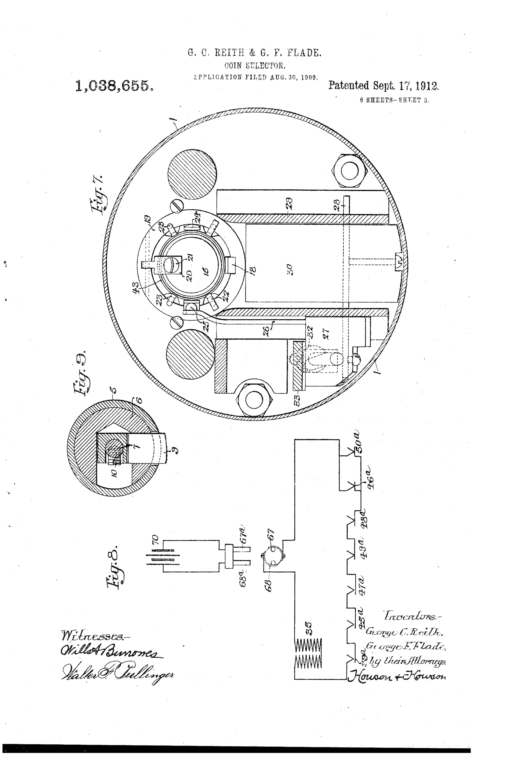
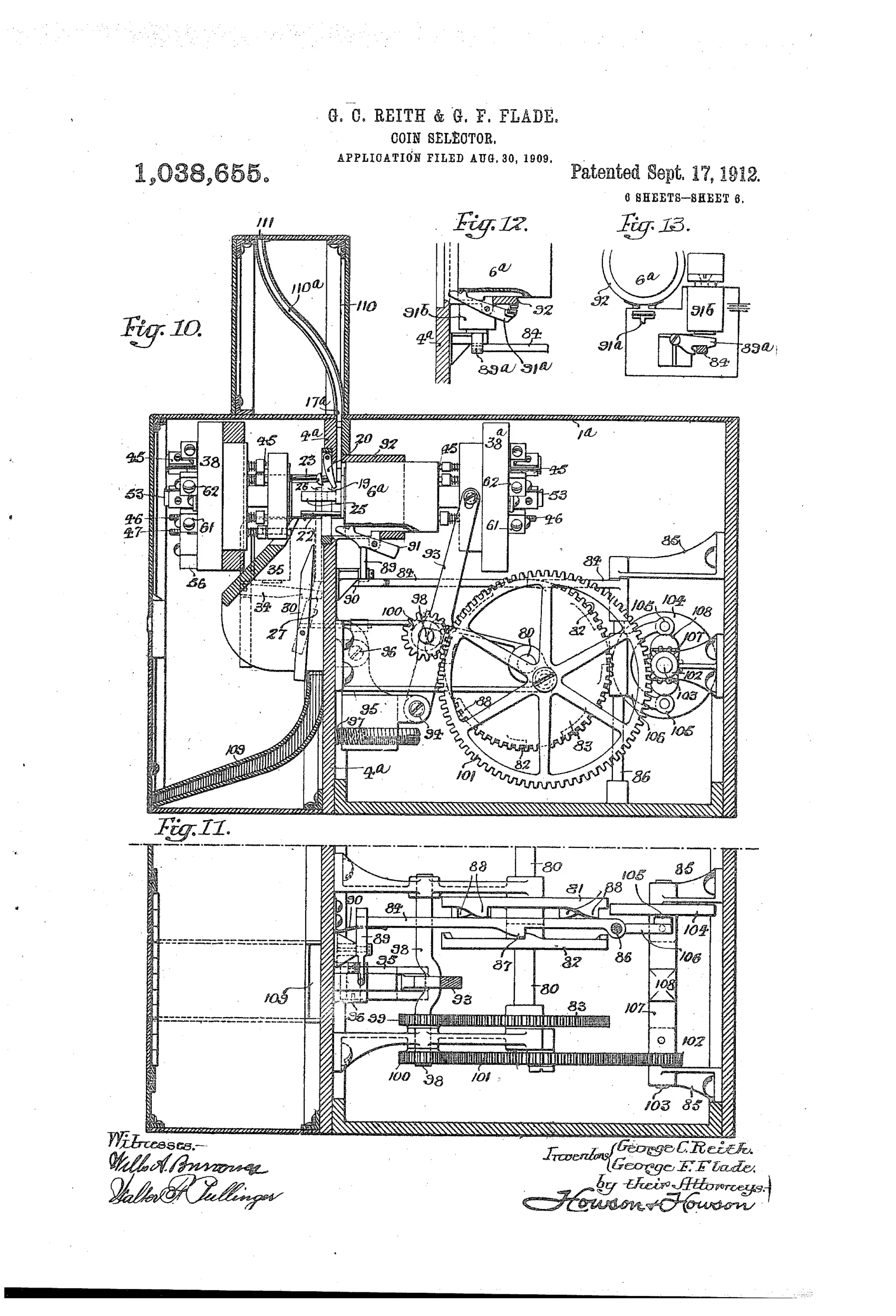
A coin dropped into a slot lands in front of a spring-backed disk on a spring-loaded plunger; when the plunger is pushed inward, a set of gauge rods and pins engage the coin's flange, thickness, and face impressions. If the coin is genuine and of standard size, the correct rods are displaced to close a series of electric switches, completing a circuit to energize an electro-magnet. The energized magnet raises an armature and catch, releasing a weighted valve plate that pivots to direct the coin into the accepted-coin passage; if the switches remain open (coin rejected), the counterweighted valve instead diverts the coin out through a reject opening in the bottom of the casing. A cam surface and offset spring member coordinate the timing of the lever arm's engagement with the valve during the plunger's inward stroke.
◉ What was claimed
“In a coin controlled machine, the combination of a chute for coins to be tested, a member movable to different positions and controlling the course of a coin through said chute, an electro-magnet operatively connected to said member, and means whose position is dependent upon the character of a coin under test for controlling the energization of said magnet.”
In plain English: The invention combines a coin chute, a movable valve controlling the coin's path, an electromagnet connected to that valve, and coin-sensing elements that determine whether the magnet is energized based on the coin's characteristics.
◉ In the inventor’s words
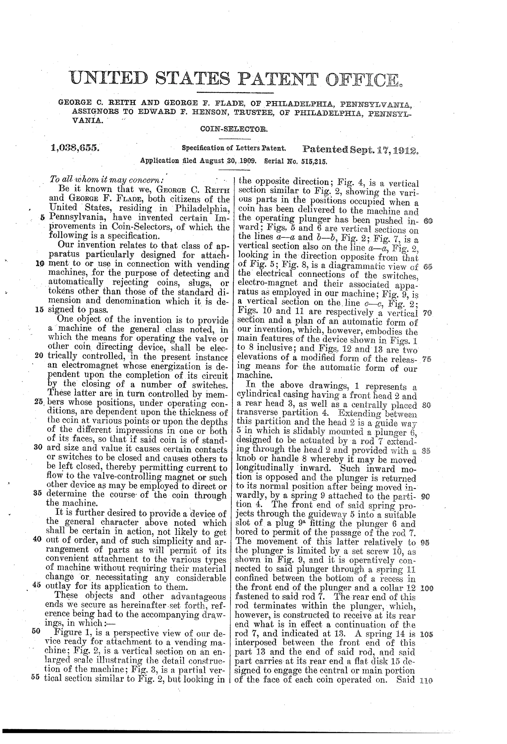
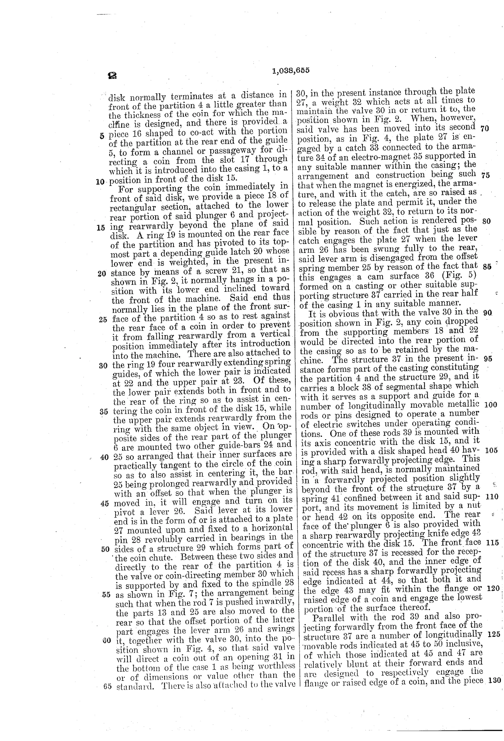
“It is further desired to provide a device of the general character above noted which shall be certain in action, not likely to get out of order, and of such simplicity and arrangement of parts as will permit of its convenient attachment to the various types of machine without requiring their material change or necessitating any considerable outlay for its application to them.”— George C. Reith and George F. Flade, from the specification
Fate unknown
The assignment to a trustee suggests commercial intent, but no marked mechanism or vending machine incorporating this design is documented; a surviving example would settle it.
◉ Commentary
By 1909 the chute-tester field was crowded with mechanical gates: rocking cradles, magnet deflectors, weight-and-diameter traps. Reith and Flade go a different route. Their coin doesn't tip a balance to earn passage — it presses against a battery of gauge rods and pins that read its flange, thickness, and even the relief of its face impressions. Only if every rod is displaced the right amount does a chain of electric switches close, energizing an electromagnet that trips the acceptance valve. The coin, in effect, has to answer several questions simultaneously, and the answer is a completed circuit.
The drawing rewards a close look at the right side of Fig. 3: that stack of numbered contacts (52, 54, 43, 55, 50, 46, 47, 56) is the switch bank, wired in series so a slug that passes on thickness but fails on face relief still stays out. The counterweighted valve is a nice fail-safe touch — its resting position rejects, and only a live magnet grants entry. Reject is the default, acceptance the exception.
The weakness is the strength: testing face impressions with feeler pins demands fine tolerances on worn, dirty coins in circulation, and any circuit fault means a machine that eats good money. Simpler mechanical rejectors and, later, conductivity tests won this race. Still, it's an early and earnest attempt at multi-parameter electrical verification — a genuine ancestor of the electronic coin validator, arriving decades before the electronics existed to make it robust.
Commentary by Claude, The Counterfeit Coin Detector Patent Archive’s resident enthusiast